
Image forming device

a technology of image forming and forming sound, which is applied in the direction of electrographic process, instruments, transportation and packaging, etc., can solve the problems of difficult to confirm the presence of paper in the manual paper supply tray and the paper discharge tray, and difficult for a user located a long distance from the image forming device to operate by means of operation sounds, etc., to achieve the effect of easy confirmation

Active Publication Date: 2005-06-30
KYOCERA DOCUMENT SOLUTIONS INC
View PDF9 Cites 28 Cited by
  • Summary
  • Abstract
  • Description
  • Claims
  • Application Information

AI Technical Summary

Benefits of technology

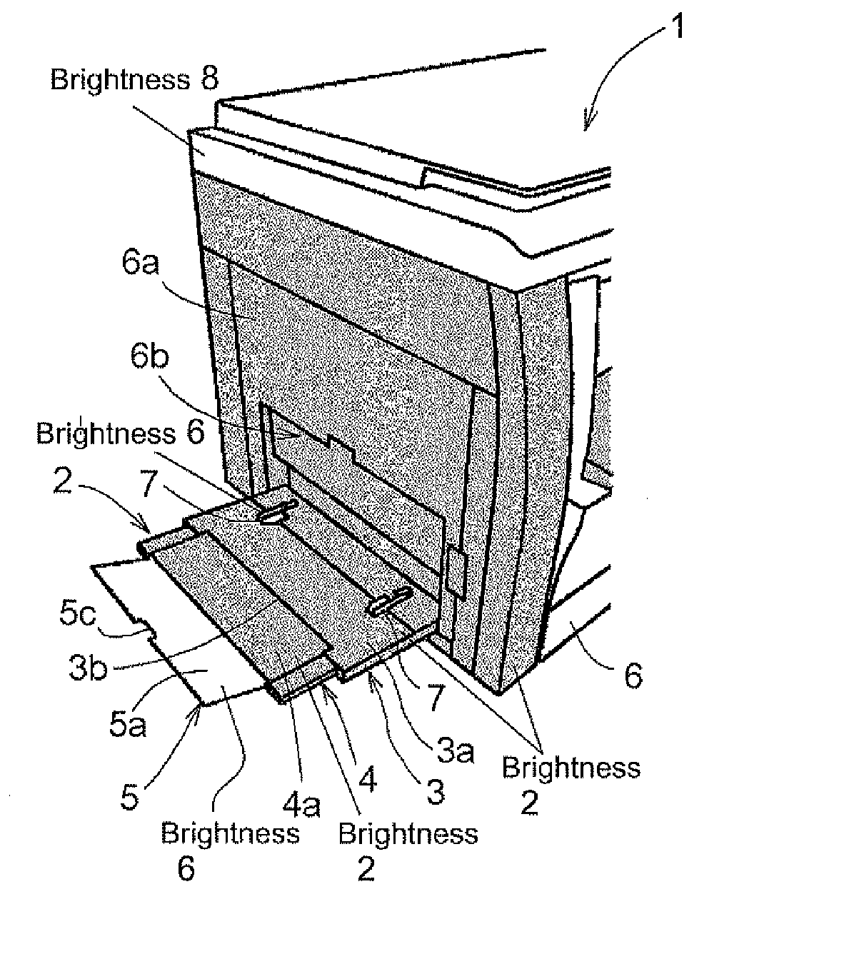
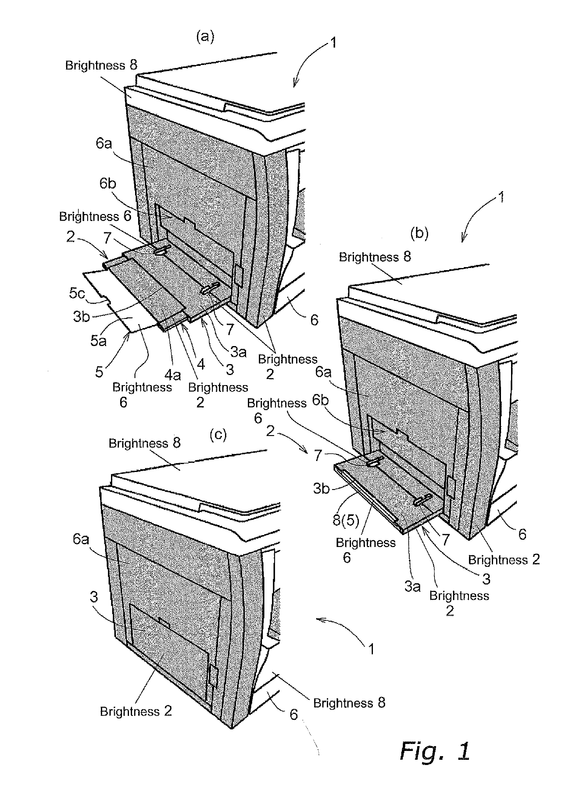
[0011] It is an object of the present invention to provide an image forming device that allows a user located some distance away from the image forming device to easily confirm the presence of paper in a paper tray thereof and the operational state of the device.
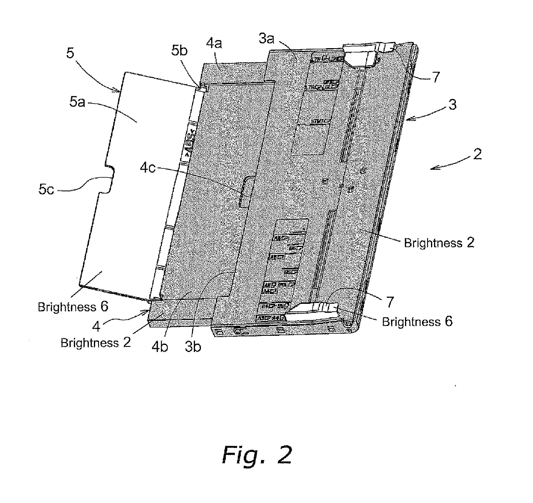
[0012] Another object of the present invention is to provide an image forming device that improves the visibility of a paper tray thereon so as to prevent one from colliding therewith, and which allows an auxiliary mounting unit of the paper tray to be easily deployed, even when the image forming device is placed in a slightly dark location.

Problems solved by technology

However, if the color of the manual paper supply tray and the discharge tray are the same color as the exterior of the image forming device, it will be difficult for a user located some distance away from the image forming device to confirm whether or not there is paper remaining in the manual paper supply tray, or confirm that paper is being discharged to the paper discharge tray, i.e., whether or not the image forming device is operating.
In particular, because the lighting in office space has in recent years been set to a slightly dark level, and because image forming devices are often placed in slightly dark, non-central locations, it is often difficult to confirm the presence of paper in the manual paper supply tray and the paper discharge tray.
Furthermore, image forming devices are now being designed for quiet operation, and thus it is often difficult for one to determine whether or not the image forming device is operating by means of operational sounds.
Thus, if an image forming device having an exterior that is a shade of black is placed in a slightly dark location, and the manual paper supply tray or the paper discharge tray extends out from a side surface of the device, there is a possibility that a person passing by this location may not notice that one or both of these trays are extended, and thus collide with and damage them.
In addition, although the manual paper supply tray and the paper discharge tray include a paper mounting unit arranged so as to be extendable and foldable with respect to a side surface of the image forming device, and an auxiliary mounting unit that is arranged so that it can slide out from the paper mounting unit, when the auxiliary mounting unit is to be pulled out from the paper mounting unit, it will be difficult for one to immediately recognize which portion one needs to grasp and pull out because the paper mounting unit and the auxiliary mounting unit are both the same color.

Method used


Image

  • Image forming device
  • Image forming device
  • Image forming device

Examples


second embodiment

[0059]FIG. 3 is an oblique view showing the configuration of a manual paper supply tray 2 of the image forming device 1 according to a second embodiment of the present invention. The configuration of the device body 6 is the same as that shown in FIG. 1. In each of the embodiments below, the same components as those in the first embodiment have the same reference numbers, and a description thereof will be omitted. Like the first embodiment, the manual paper supply tray 2 of the second embodiment includes a first auxiliary mounting unit 4 and a second auxiliary mounting unit 5 configured to be deployable in two steps from the paper mounting unit 3. However, the specific configuration of the first auxiliary mounting unit 4 and the second auxiliary mounting unit 5 in the second embodiment is different. In other words, in the present embodiment, the second auxiliary unit 5 is configured so as to be stored in the first auxiliary mounting unit 4, and is pulled out horizontally with the fi...

third embodiment

[0061]FIG. 4 is an oblique view showing the configuration of a manual paper supply tray 2 of the image forming device 1 according to a third embodiment of the present invention. The configuration of the device body 6 is the same as that shown in FIG. 1. In each of the embodiments below, the same components as those in the first embodiment have the same reference numbers, and a description thereof will be omitted. Like the first embodiment, the manual paper supply tray 2 of the third embodiment includes a first auxiliary mounting unit 4 and a second auxiliary mounting unit 5 configured to be deployable in two steps from the paper mounting unit 3. However, the specific configuration of the second auxiliary mounting unit 5 in the third embodiment is different. In other words, in the third embodiment, the second auxiliary mounting unit 5 is arranged on top of the first auxiliary mounting surface 4a of the first auxiliary mounting unit 4, and can be deployed by pivoting around a rotation...

fourth embodiment

[0063]FIG. 5 is an oblique view showing the configuration of a manual paper supply tray 4 of the image forming device 1 according to a fourth embodiment of the present invention. The configuration of the device body 6 is the same as that shown in FIG. 1. In each of the embodiments below, the same components as those in the first embodiment have the same reference numbers, and a description thereof will be omitted. Like the first embodiment, the manual paper supply tray 2 of the fourth embodiment includes a first auxiliary mounting unit 4 and a second auxiliary mounting unit 5 configured to be deployable in two steps from the paper mounting unit 3. However, the specific configuration of the first auxiliary mounting unit 4 and the second auxiliary mounting unit 5 in the fourth embodiment is different. In other words, in the present embodiment, the second auxiliary unit 5 is configured so as to be stored in the first auxiliary mounting unit 4, and is pulled out horizontally with the fi...


PUM


Abstract

An image forming device includes an image forming device body having an image forming unit in the interior thereof, and at least one paper tray attached to the image forming device on which paper is to be mounted. The paper tray includes a paper mounting unit having a paper mounting surface on which paper is to be mounted, and at least one movable auxiliary mounting unit. The auxiliary mounting unit is supported by the paper mounting unit, and includes an auxiliary mounting surface that is deployed from the paper mounting unit and which serves to extend the mounting surface. The brightnesses of the mounting surface and the auxiliary mounting surface of the paper tray are lower than the brightness of the paper to be mounted on each mounting surface, and the brightness of at least a portion of the auxiliary mounting surface is higher than the brightness of the mounting surface.

Description

BACKGROUND OF THE INVENTION [0001] 1. Field of the Invention [0002] The present invention relates to an image forming device such as a facsimile device, a printer, or the like, and in particular to an image forming device comprised of a paper tray having a movable auxiliary mounting unit that can be deployed from a paper mounting unit. [0003] 2. Background Information [0004] Generally speaking, image forming devices such as copying machines, facsimile devices, printers and the like are provided with a paper supply cassette that stores paper for recording images thereon, and a manual paper supply tray that allows a user to supply paper of a different orientation or size than that stored in the paper supply cassette. One type of prior art manual paper supply tray for an image forming device includes a paper mounting unit arranged so as to be extendable and foldable with respect to a side surface of the image forming device, and an auxiliary mounting unit that is arranged so that it ca...

Claims


Application Information

Patent Timeline
IPC IPC(8): G03G15/00B65H11/00H04N1/04
CPCG03G15/6552G03G15/6502
Inventor KAWASHIMA, TETSURO
Owner KYOCERA DOCUMENT SOLUTIONS INC
Learn More