Separator for fuel cell

a fuel cell and separator technology, applied in the field of fuel cell separators, can solve the problems of affecting the production efficiency of separators, affecting the efficiency of fuel cell production, so as to eliminate the trouble of incorporating passage gaskets and form easily in a short time.

Inactive Publication Date: 2005-06-30
HONDA MOTOR CO LTD
View PDF3 Cites 34 Cited by
  • Summary
  • Abstract
  • Description
  • Claims
  • Application Information

AI Technical Summary

Benefits of technology

[0021] Also, in this invention, preferably, projecting passage seal parts severally surrounding the gas passages and the reaction product passages are provided on the peripheral part. When projecting passage seal parts severally surrounding the gas passages and the reaction product passages are provided on the peripheral part like this, in the assembling of the separator, it is not necessary to incorporate passage gaskets for surrounding the gas passages and the reaction product passages. As a result, in the assembling of a fuel cell, it is possible to eliminate the trouble of incorporating passage gaskets. Furthermore, in the assembling of the separator, the gas passages and reaction product passages can be surely sealed with the projecting passage seal parts.
[0022] Also, in the invention, preferably, the elastic member and the central seal part are formed integrally from a rubber material. When the elastic member and the central seal part are formed integrally from a rubber material like this, these members can be formed simultaneously. Consequently, the elastic member and the central seal part can be formed easily in a short time.

Problems solved by technology

And even if the precision of the equipment is raised, it is difficult to cover the entire surfaces of the gas passages and product water passages of the peripheral part 113a with the seal 115, and yield in the manufacture of the separators is likely to fall, and this has constituted a hindrance to raising fuel cell productivity.

Method used


Image

  • Separator for fuel cell
  • Separator for fuel cell
  • Separator for fuel cell

Examples


Embodiment Construction

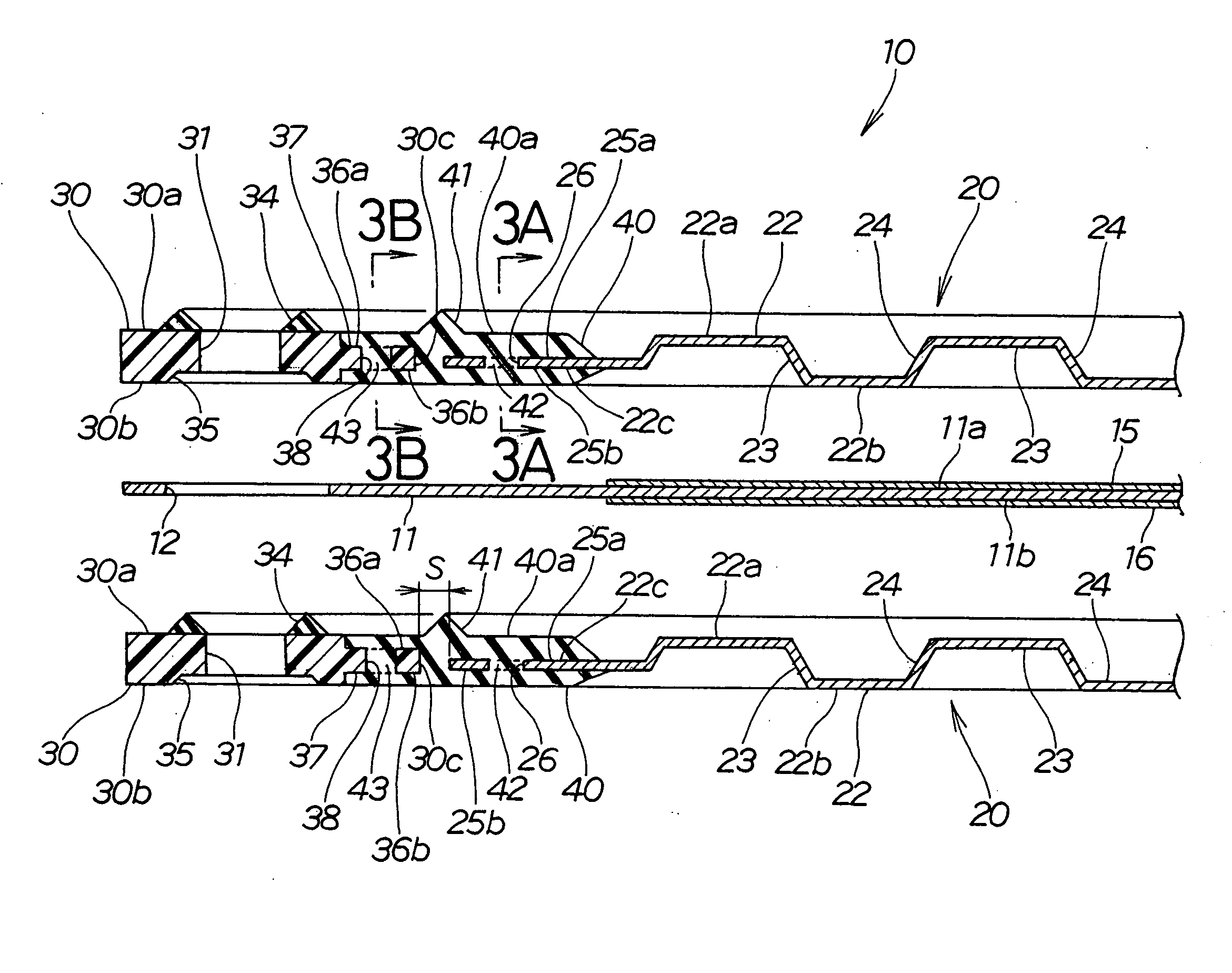
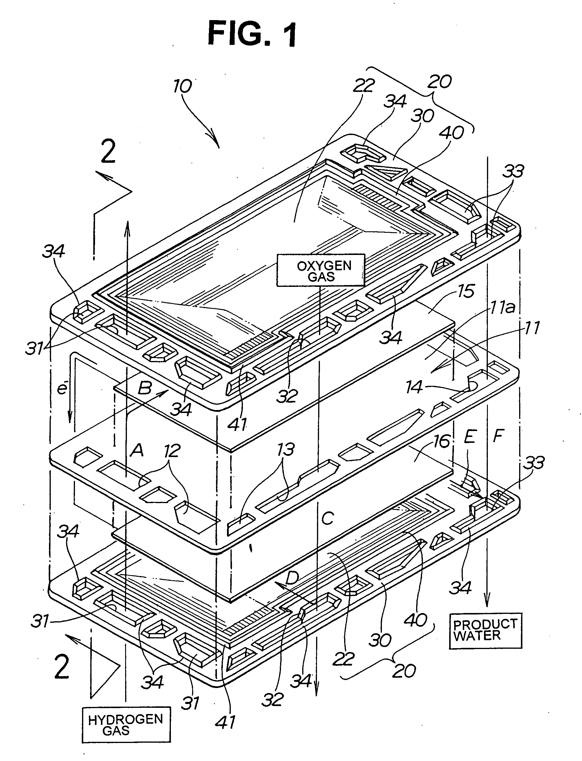
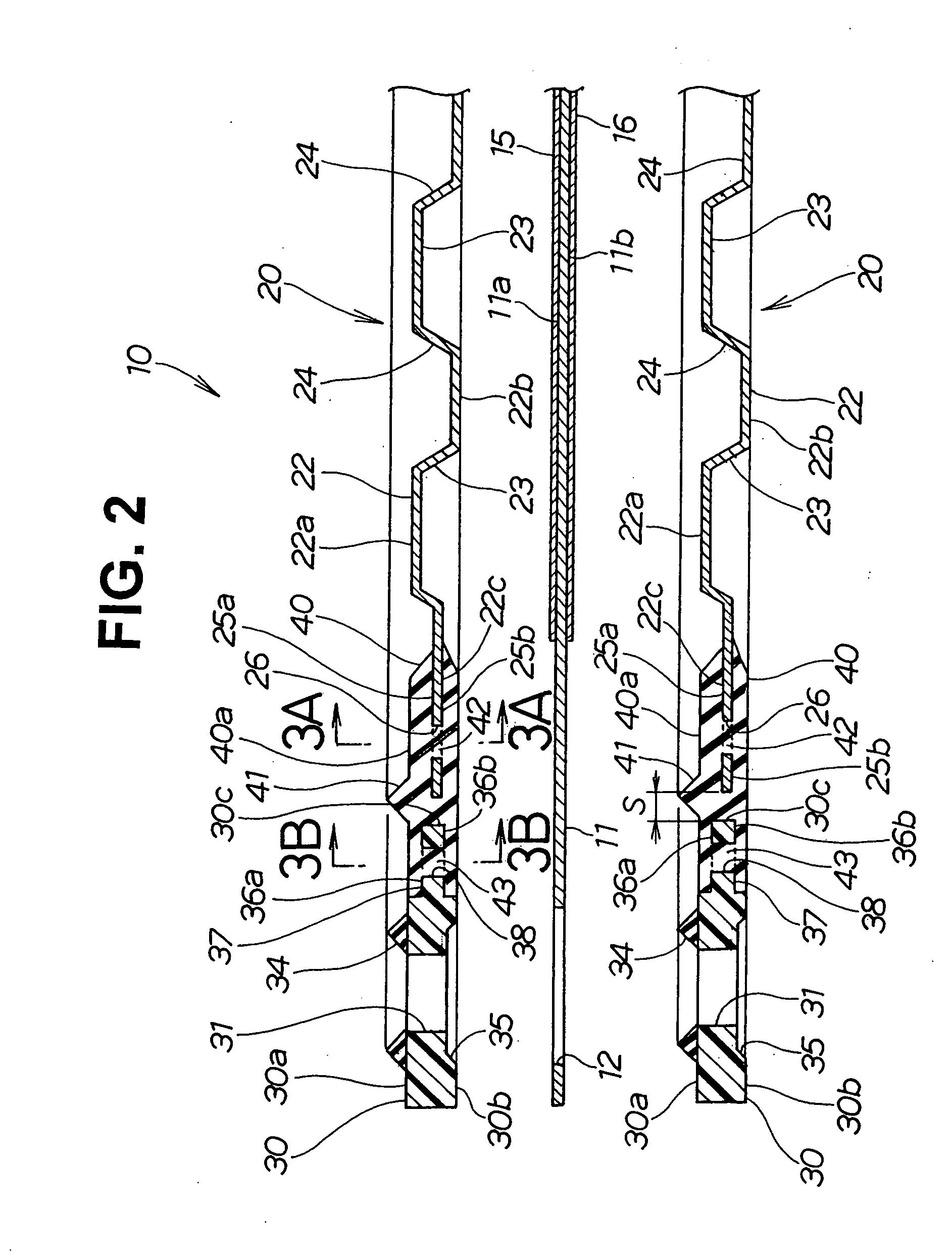
[0034] A fuel cell 10 according to the invention shown in FIG. 1 has a structure wherein a negative electrode 15 and a positive electrode 16 are respectively disposed on the upper face 11a side and the lower face 11b (see FIG. 2) side of an electrolyte membrane 11 and an upper side separator 20 (fuel cell separator) is superposed on the negative electrode 15 and a lower side separator 20 is superposed on the positive electrode 16.

[0035] Here, generally the fuel cell 10 made by stacking the electrolyte membrane 11, the negative electrode 15, the positive electrode 16 and the upper and lower separators 20, 20 is referred to as a cell, and multiple cells arrayed in a stack are referred to as a fuel cell; however, in this specification, to facilitate understanding, the cell will be called a fuel cell.

[0036] In a peripheral part thereof, the electrolyte membrane 11 has multiple hydrogen gas passages (gas passages) 12 for guiding hydrogen gas (a reaction gas), multiple oxygen gas passag...


PUM

PropertyMeasurementUnit
temperatureaaaaaaaaaa
elasticaaaaaaaaaa
timeaaaaaaaaaa

Abstract

A fuel cell separator is provided which has in a peripheral part (30) gas passages (31, 31) for guiding reaction gases and reaction product passages (33) for guiding a reaction product. The separator (20) is made up of a central part (22) made of metal, a peripheral part (30) made of a resin material, and an elastic member (40) connecting the central part and the peripheral part together. As a result of the peripheral part being made of a resin material, the gas passages and product passages are resistant to corrosion.

Description

TECHNICAL FIELD [0001] This invention relates to a fuel cell separator having multiple passages provided in a peripheral part of the separator and used to guide reaction gases and a reaction product. BACKGROUND ART [0002]FIG. 10 shows a fuel cell of related art. This fuel cell 100 is made by disposing a negative electrode 102 and a positive electrode 103 respectively on the upper face side and the lower face side of an electrolyte membrane 101, placing a separator 105 on the upper side of the negative electrode 102 and sandwiching the peripheral vicinity of the electrolyte membrane 101 and the peripheral vicinity of the upper side separator 105 with an upper side gasket 106, and placing a separator 105 on the lower side of the positive electrode 103 and sandwiching the peripheral vicinity of the electrolyte membrane 101 and the peripheral vicinity of the lower side separator 105 with a lower side gasket 106. [0003] With this fuel cell 100, hydrogen gas is supplied through multiple h...

Claims


Application Information

Patent Timeline
Patent Type & Authority Applications(United States)
IPC IPC(8): H01M8/02H01M8/10
CPCH01M8/0206H01M8/0247Y02E60/50H01M8/0271H01M8/0254H01M8/02H01M8/10
Inventor KIMURA, MIKIHIKOKAWACHI, SHINYAANDOU, KEISUKENISHIYAMA, TADASHIOKONOGI, DAISUKE
Owner HONDA MOTOR CO LTD
Why Eureka
Try Eureka