Operational status display system for analyzing apparatus

a status display and analyzing apparatus technology, applied in material analysis, instruments, measurement devices, etc., can solve problems such as ineffectiveness and bothersomeness, and achieve the effect of eliminating troubles

Inactive Publication Date: 2010-09-02
SHIMADZU CORP
View PDF5 Cites 23 Cited by
  • Summary
  • Abstract
  • Description
  • Claims
  • Application Information

AI Technical Summary

Benefits of technology

[0013]With the operational status display system for an analyzing apparatus according to the present invention, an analyzing apparatus arrangement image in which an arrangement position of an analyzing apparatus is presented is displayed on the display of a client for analysis, which is often installed separately from the analyzing apparatus. Therefore, the user can visually recognize the position where the analyzing apparatus is installed. Hence, when the user operates an analyzing apparatus composed of a client terminal, for example, a client terminal and goes to the corresponding analyzing apparatus to set a sample, the user can eliminate troubles such as: the user goes to a wrong analyzing apparatus and the user has to locate its installation location.
[0014]In the case where the client for analysis has an operational status image creator, the operational status of each image apparatus is constantly updated and displayed on the operational status image. Therefore, the user can determine the current status of the analyzing apparatus in real time without opening a list which shows the operational status.
[0015]In the case where the client for analysis has a setting window displayer, when the user performs an input operation such as a click with a specifier such as a mouse pointer being placed on an apparatus image in the window in which the operational status image is displayed, a setting window for the analyzing apparatus corresponding to the apparatus image is instantly displayed. This leads to a smooth and more intuitive operation.

Problems solved by technology

For this reason, in the case where many analyzing apparatuses are installed and their installation locations are separated from each other, it is necessary to check around each analyzing apparatus to know the progresses of all analyzing apparatuses, which is very bothersome and ineffective.

Method used


Image

  • Operational status display system for analyzing apparatus
  • Operational status display system for analyzing apparatus
  • Operational status display system for analyzing apparatus

Examples


Embodiment Construction

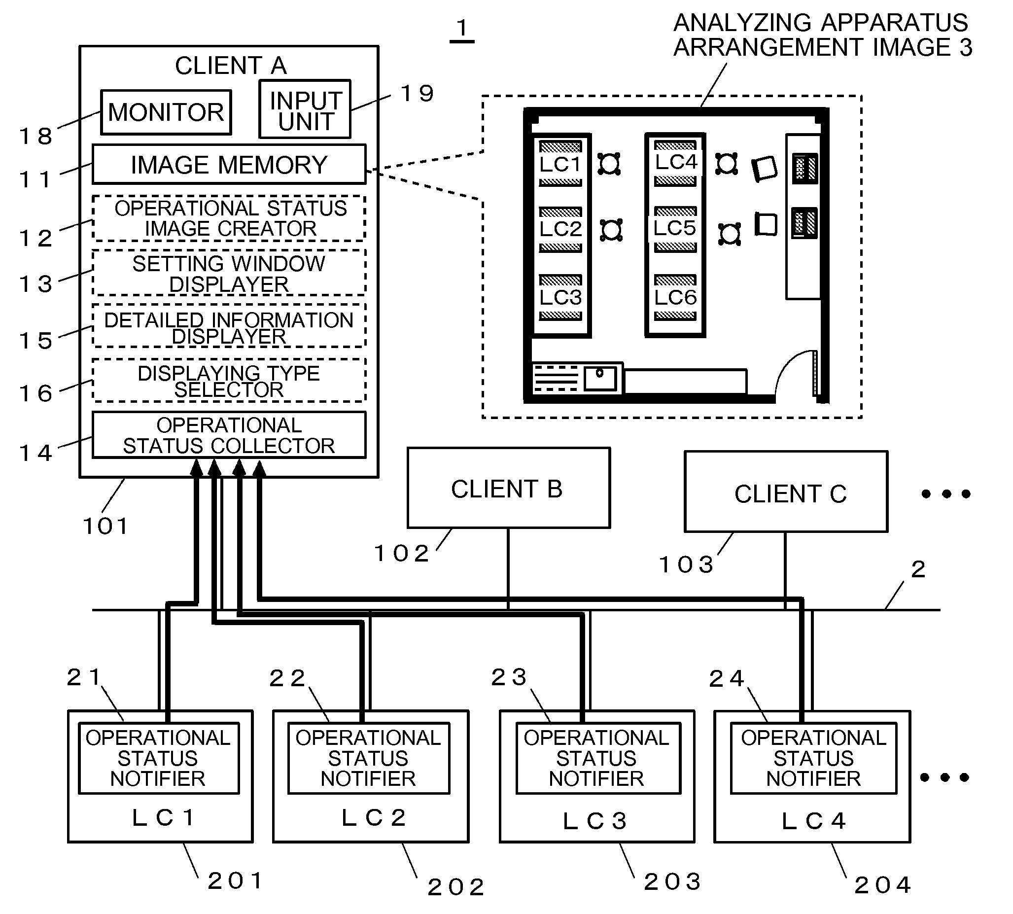
[0036]FIG. 1 is a block diagram illustrating a schematic configuration of an embodiment of the operational status display system for an analyzing apparatus according to the present invention. The system 1 according to the present embodiment includes a client for analysis A101, client B102, . . . , and a plurality of analyzing apparatuses 201, 202, . . . , which are connected to a data communication network 2 such as a local area network (LAN). Although only four analyzing apparatuses are illustrated in FIG. 1, the following explanation supposes that six analyzing apparatuses are connected to the network.

[0037]The clients 101, 102, . . . are normally a PC which includes a storage media such as a hard disk in which programs and data are stored in advance, a monitor 18 such as a cathode ray tube (CRT) display or a liquid crystal display, and an input unit 19 such as a keyboard having character and number input keys, various function keys, and other keys, and a mouse which is a pointing...


PUM


Abstract

In an analyzing system including a plurality of analyzing apparatuses and an operational status collector for collecting the analyzing apparatus' operational status by way of a data communication network, each status of the plurality of analyzing apparatuses is conventionally displayed in the form of a list. This causes a problem that there is no knowing the installation position of an actual analyzing apparatus from a client for analysis which is installed separately from the analyzing apparatus. In the operational status display system for an analyzing apparatus according to the present invention, an analyzing apparatus arrangement image is displayed in which the arrangement positions of the analyzing apparatuses are illustrated with apparatus images. The user can easily grasp the actual arrangement position of an analyzing apparatus. Alternatively, each analyzing apparatus' operational status may be displayed on the apparatus image. With this configuration, it is possible to know each analyzing apparatus' operational status. Furthermore, a click of an apparatus image may display a detail setting window, which can smooth the control operation.

Description

TECHNICAL FIELD[0001]The present invention relates to a system for remotely monitoring an analyzing apparatus such as a liquid chromatograph and mass spectrometer. In particular, the present invention relates to a system for remotely monitoring the operational status of a plurality of apparatuses connected to a network.BACKGROUND ART[0002]In a liquid chromatograph, for example, in performing an analysis for a plurality of samples, an analysis schedule in which vial numbers and injection volumes in an auto-sampler are set for example is specified. Then samples are sequentially taken from the auto-sampler in accordance with the schedule to perform an analysis to obtain analysis data. In general, an operator can check the progress of an analysis in accordance with a schedule on the window shown on the display of the analyzing apparatus. In recent years, a personal computer (which will be hereinafter called “PC” using the short form) has often been used as a data processing and / or contr...

Claims


Application Information

Patent Timeline
Patent Type & Authority Applications(United States)
IPC IPC(8): G06F3/048G06F15/16
CPCG01N30/88G01N2035/00891G01N2030/8804G01N35/00871
Inventor WAKABAYASHI, KAZUHITONISHIMOTO, RYUJI
Owner SHIMADZU CORP
Why Eureka
Try Eureka