An electronic vehicle battery replacement system

a technology for electronic vehicles and batteries, applied in the direction of battery/cell propulsion, vehicle maintenance, electric propulsion mounting, etc., can solve the problems of limited use and promotion of electric vehicles, no effective alternative energy for automobiles, and great challenges for human beings for living and development, so as to reduce the weight of electric vehicles, and prevent electric shocks of operators

Inactive Publication Date: 2015-10-22
ZHANG WUJIE
View PDF10 Cites 23 Cited by
  • Summary
  • Abstract
  • Description
  • Claims
  • Application Information

AI Technical Summary

Benefits of technology

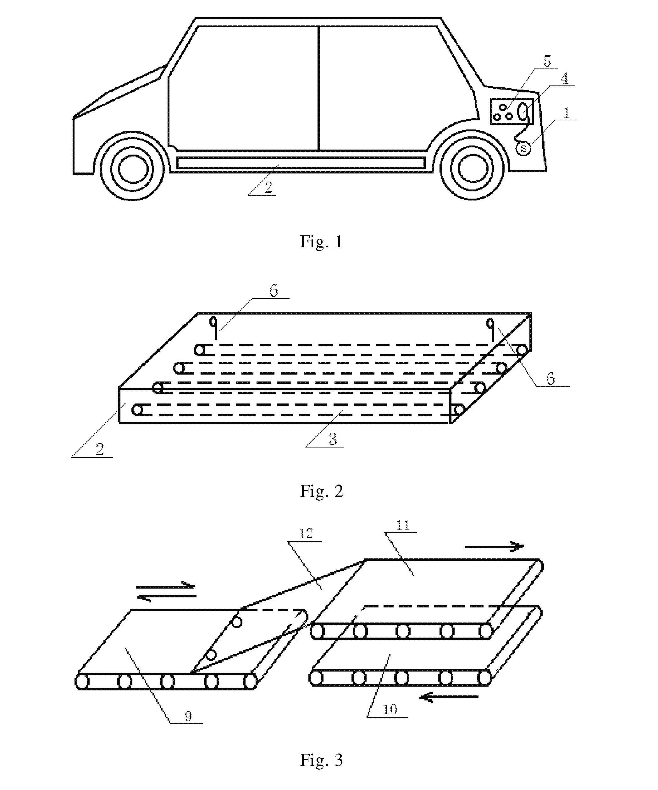
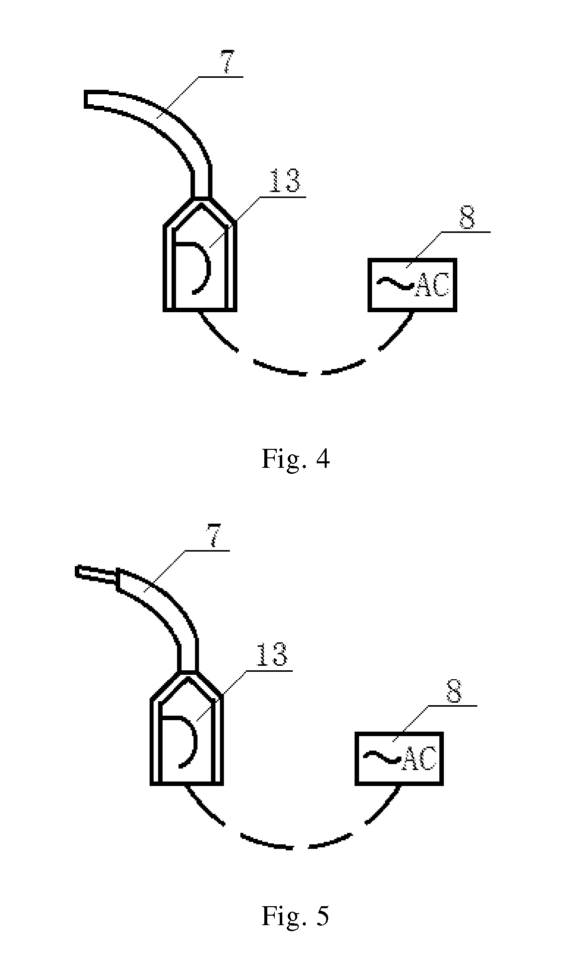
[0007]According to some embodiments, in the above-described electric vehicle battery replacement system, the body of the vehicle comprises a charging port connected with the drive motor for insertion of and connection with a transmission gun. According to some embodiments, the head of the transmission gun comprises a plug structure matching a socket within the charging port and outside the plug is a retractable cover. Provision of the external transmission gun reduces self-carried power source of the electric vehicle and thus reduces the weight of the electric vehicle. The retractable cover outside the plug can protect the plug and prevent electric shock of an operator.
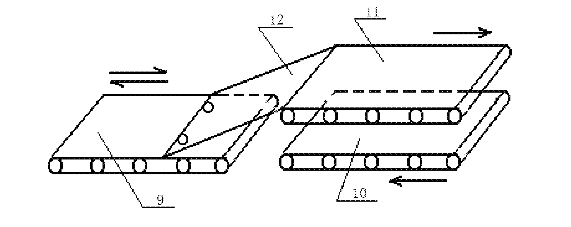
[0008]According to some embodiments, in the above-described electric vehicle battery replacement system, one end of the sliding plate is hinged on the front end of the third conveying belt, and the other end of the sliding plate comprises a roller which is placed on the first conveying belt. The function of the roller is to prevent friction between the sliding plate and the first conveying belt.
[0009]According to some embodiments, in the above-mentioned electric vehicle battery replacement system, the vehicle-mounted battery driving device comprises a fixed limit switch connected with the drive motor. When a battery is carried to a predetermined position within the body of the vehicle, the limit switch is pushed, thereby cutting off power to the drive motor so that the drive motor stops working. The function of the limit switch is to prevent the battery from being drawn by the drive roller beyond the predetermined position and thus causing damage to other devices.
[0010]According to some embodiments, in the above-mentioned electric vehicle battery replacement system, each of the three conveying motors is connected with a central control computer. A gravity sensor is also fixed below each of the first conveying belt, the second conveying belt, and the third conveying belt, and each of the three gravity sensors is connected to the central control computer. The sensors installed below the conveying belts can transmit signals they obtain to the central control computer, thereby allowing the central control computer to successively initiate the forward rotation of the conveying motors connected with the first conveying belt and the third conveying belt. Then the central control computer can initiate the reverse rotation of the conveying motors connected with the first conveying belt and the second conveying belt, thereby allowing a new battery to be carried in along the second conveying belt, through below the jacked sliding plate, and then along the first conveying belt.
[0011]The present disclosure provides a new battery replacement system for electric vehicles, which can realize fast and efficient replacement of electric vehicles' batteries, and eliminate the trouble brought by long charging time of the batteries.

Problems solved by technology

As the non-renewable energy resources such as petroleum and natural gas are being exhausted and the technology of utilizing such clean energies as solar energy and wind energy is far from mature, the human beings are facing great challenges for living and development.
Currently, there is no effective alternative energy for automobiles.
However, the use and promotion of electric vehicles are largely restricted due to such factors as the limited battery capacity and long charging time.

Method used


Image

  • An electronic vehicle battery replacement system
  • An electronic vehicle battery replacement system
  • An electronic vehicle battery replacement system

Examples


Embodiment Construction

[0018]The following description is presented to enable a person of ordinary skill in the art to make and use the various embodiments. Descriptions of specific devices, techniques, and applications are provided only as examples. Various modifications to the examples described herein will be readily apparent to those of ordinary skill in the art, and the general principles defined herein may be applied to other examples and applications without departing from the spirit and scope of the various embodiments. Thus, the various embodiments are not intended to be limited to the examples described herein and shown, but are to be accorded the broadest scope consistent with the claims.

[0019]In the following description of embodiments, reference is made to the accompanying drawings which form a part hereof, and in which it is shown by way of illustration specific embodiments of the disclosure that can be practiced. It is to be understood that other embodiments can be used and structural chang...


PUM


Abstract

The present disclosure discloses an electric vehicle battery replacement system comprising a vehicle-mounted battery driving device and a battery conveying device outside of the vehicle. The vehicle-mounted battery driving device comprises a drive roller configured to carry a battery and connected with a drive motor. The battery conveying device outside of the vehicle comprises three conveying belts each connected to one of three conveying motors, respectively. The drive roller, a first conveying belt, and a second conveying belt are arranged successively on a same horizontal plane along a direction of conveying. The third conveying belt is located above the second conveying belt and connected with the first conveying belt via a sliding plate. One end of the sliding plate connects flexibly to a front end of the third conveying belt, and the other end of the sliding plate is placed on the first conveying belt. The battery replacement system provided in the present disclosure solves such problems as long charging time and low efficiency in public charging stations by using the current charging method of existing electric vehicles, and meets the growing demand of the increasing number of electric vehicles.

Description

TECHNICAL FIELD[0001]The present invention belongs to the field of electric vehicle devices, and particularly relates to an electronic vehicle battery replacement system.BACKGROUND[0002]As the non-renewable energy resources such as petroleum and natural gas are being exhausted and the technology of utilizing such clean energies as solar energy and wind energy is far from mature, the human beings are facing great challenges for living and development. Every day, hundreds of millions of automobiles in the world are consuming a substantial proportion of petroleum and natural gas. Currently, there is no effective alternative energy for automobiles. If the electric power carried by batteries can be used as a substitute for petroleum and natural gas to drive automobiles, not only can the service duration of petroleum be greatly prolonged, but also emission from automobiles can be reduced. Though such energy resources as coal, petroleum and natural gas are consumed and harmful gases to the...

Claims


Application Information

Patent Timeline
Patent Type & Authority Applications(United States)
IPC IPC(8): B60S5/06B60K1/04B65G15/22
CPCB60S5/06B65G15/22B60K2001/0455B60K2001/0438B60K1/04B60K2001/0461B60K2001/0494Y02T10/7072B60L53/80B60L50/66Y02T10/70Y02T90/14Y02T10/64Y02T90/12
Inventor ZHANG, WUJIE
Owner ZHANG WUJIE
Why Eureka
Try Eureka