
Microneedle arrays and methods of manufacturing the same

a technology of microneedle arrays and needles, which is applied in the field of microneedle arrays, can solve the problems of difficult manufacturing of passageways, difficult to manufacture passageways, and easy obstruction or clogging of passageways

Inactive Publication Date: 2005-06-30
3M INNOVATIVE PROPERTIES CO
View PDF25 Cites 162 Cited by
  • Summary
  • Abstract
  • Description
  • Claims
  • Application Information

AI Technical Summary

Benefits of technology

The present invention provides microneedle arrays with channels that can help deliver or remove fluids, as well as methods for manufacturing the arrays. The microneedles have a tapered shape with a base and tip, and the channels are formed in the outer surface of each microneedle. The microneedle arrays can be used for penetrating skin to deliver medications or extract blood or tissue, and the channels can improve the delivery or removal of fluids. The microneedle arrays can also be used in conjunction with devices that can apply an impact force to the array to effectively pierce the stratum corneum. The invention also provides a microneedle device with elongated bases for improved rigidity and structural integrity, as well as a method for delivering the microneedle array to a skin impact site by applying an impact force.

Problems solved by technology

Because the needles are themselves small, the passageways formed in the needles must be limited in size.
As a result, the passageways can be difficult to manufacture because of their small size and the need for accurate location of the passageways within the needles.
Another potential problem of passageways small enough to fit within the microneedles is that the passageways may become easily obstructed or clogged during use.
One problem associated with penetration of skin by microneedle arrays is, however, the viscoelastic properties of skin.
Such devices are, however, relatively painful to use and may pose a risk of inadvertent piercing of skin.
Further, the pierced site may experience unnecessary bleeding.

Method used


Image

  • Microneedle arrays and methods of manufacturing the same
  • Microneedle arrays and methods of manufacturing the same
  • Microneedle arrays and methods of manufacturing the same

Examples


Embodiment Construction

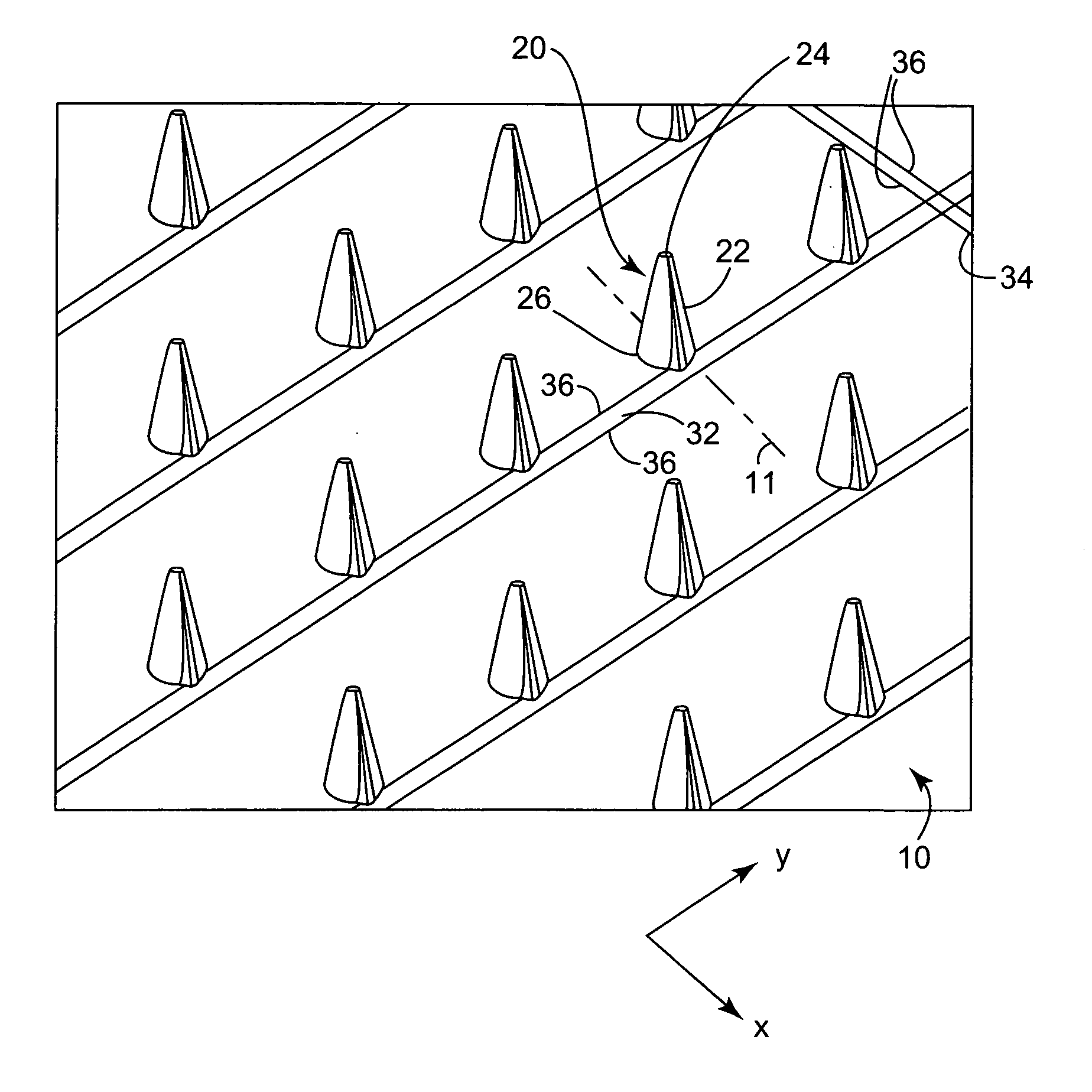
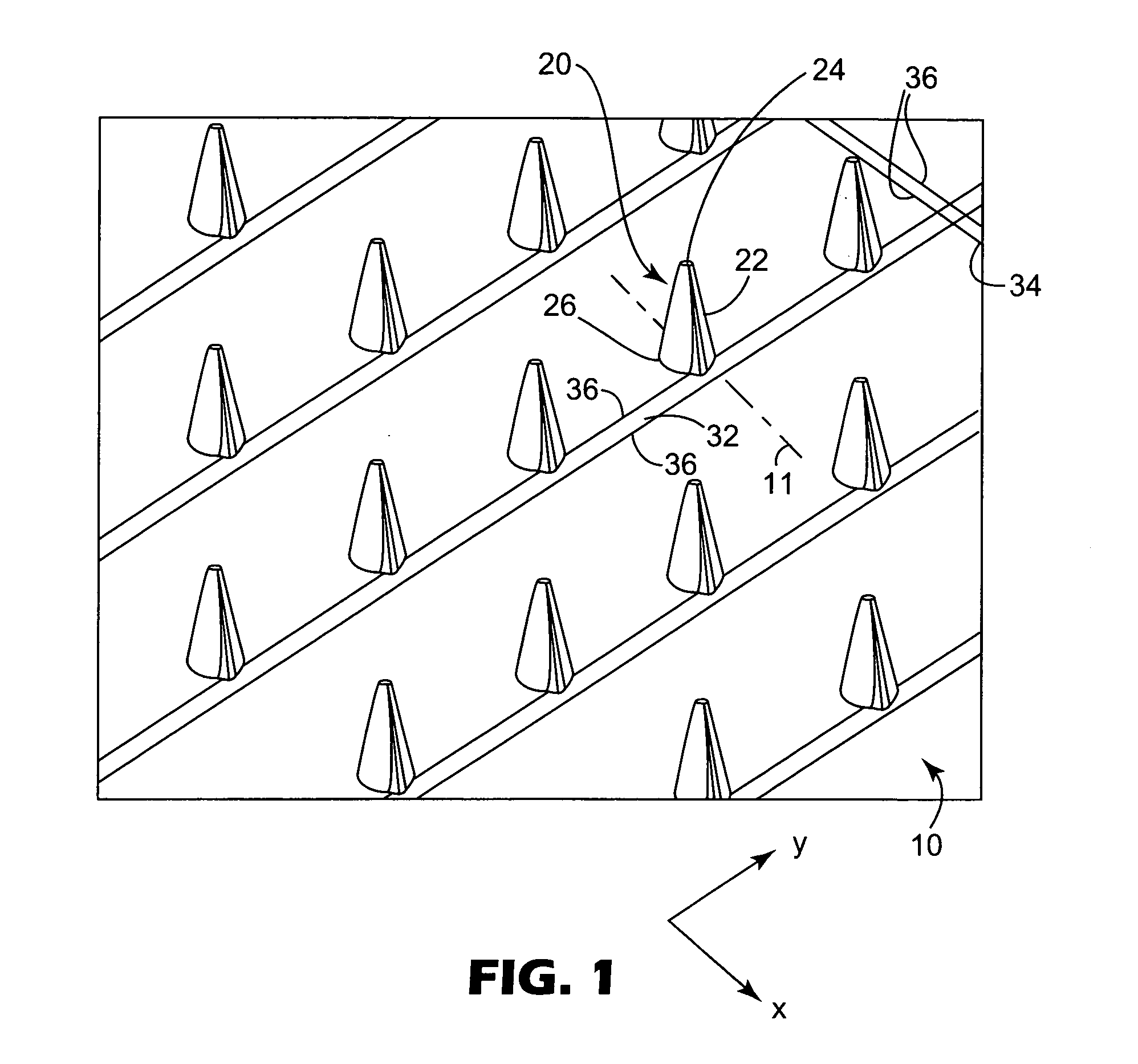
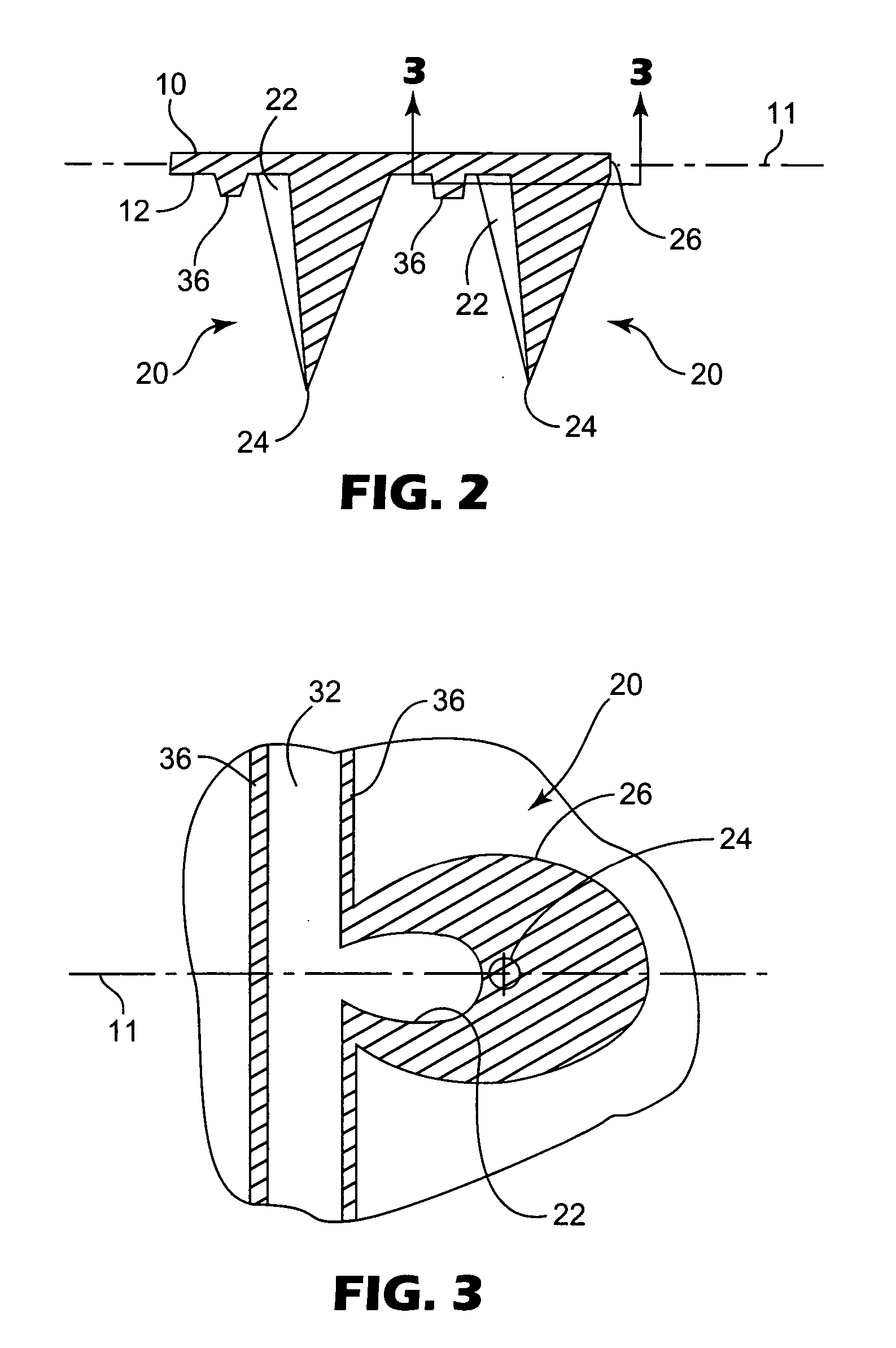
[0035] The present invention provides a microneedle array that may be useful for a variety of purposes. For example, the microneedles may be used to deliver or remove fluids from the point at which they are inserted. To accomplish that goal, the microneedles include a channel formed in the outer surface of a tapered structure. The channel extends from a base or near a base of the microneedle towards the tip of the microneedle. The channel is typically formed as a void running along the side of the microneedle. In some embodiments, the channel may extend to the tip of the microneedle and, in other embodiments, the channel may terminate before reaching the tip.

[0036] The channels formed in microneedles of the present invention can be distinguished from bores or vias formed in known microneedles because they are open along substantially their entire length, e.g., from the base of the microneedle to the terminus of the channel. In contrast, bores or vias formed in known microneedles ty...


PUM


Abstract

Microneedle arrays, methods of manufacturing microneedles and methods of using microneedle arrays. The microneedles in the microneedle arrays may be in the form of tapered structures that include at least one channel formed in the outside surface of each microneedle. The microneedles may have bases that are elongated in one direction. The channels in microneedles with elongated bases may extend from one of the ends of the elongated bases towards the tips of the microneedles. The channels formed along the sides of the microneedles may optionally be terminated short of the tips of the microneedles. The microneedle arrays may also include conduit structures formed on the surface of the substrate on which the microneedle array is located. The channels in the microneedles may be in fluid communication with the conduit structures. One manner of using microneedle arrays of the present invention is in methods involving the penetration of skin to deliver medicaments or other substances and / or extract blood or tissue.

Description

CROSS REFERENCE TO RELATED APPLICATIONS [0001] This application is a divisional U.S. Ser. No. 09 / 947,195, filed Sep. 5, 2001, now allowed, the disclosure of which is herein incorporated by reference.FIELD OF INVENTION [0002] The present invention relates to the field of microneedle arrays. BACKGROUND [0003] Arrays of relatively small structures, sometimes referred to as microneedles or micro-pins, have been disclosed for use in connection with the delivery and / or removal of therapeutic agents and other substances through the skin and other surfaces. [0004] The vast majority of known microneedle arrays include structures having a capillary or passageway formed through the needle. Because the needles are themselves small, the passageways formed in the needles must be limited in size. As a result, the passageways can be difficult to manufacture because of their small size and the need for accurate location of the passageways within the needles. [0005] Another potential problem of passa...

Claims


Application Information

Patent Timeline
Patent Type & Authority Applications(United States)
IPC IPC(8): A61M37/00
CPCA61B5/1411A61B2562/0295A61M37/0015A61B5/14514A61M2037/003A61M2037/0038A61M2037/0053A61M2037/0007A61B5/150022A61B5/150099A61B5/150229A61B5/150282A61B5/150358A61B5/150969A61B5/150984
Inventor DELMORE, MICHAEL D.FLEMING, PATRICK R.HUNTLEY, DOUGLAS A.KEISTER, JAMIESON C.THOMAS, CRISTINA U.FERBER, RICHARD H.
Owner 3M INNOVATIVE PROPERTIES CO
Learn More