
Bone fixation system with radially extendable anchor

a technology radial extension, which is applied in the field of bone fixation system, can solve the problems of inflicting trauma to adjacent tissue, increasing the difficulty of pin removal, and affecting the service life of k-wire fixation, and causing disruption or damage to adjacent structures

Inactive Publication Date: 2005-06-30
TRIAGE MEDICAL
View PDF77 Cites 188 Cited by
  • Summary
  • Abstract
  • Description
  • Claims
  • Application Information

AI Technical Summary

Benefits of technology

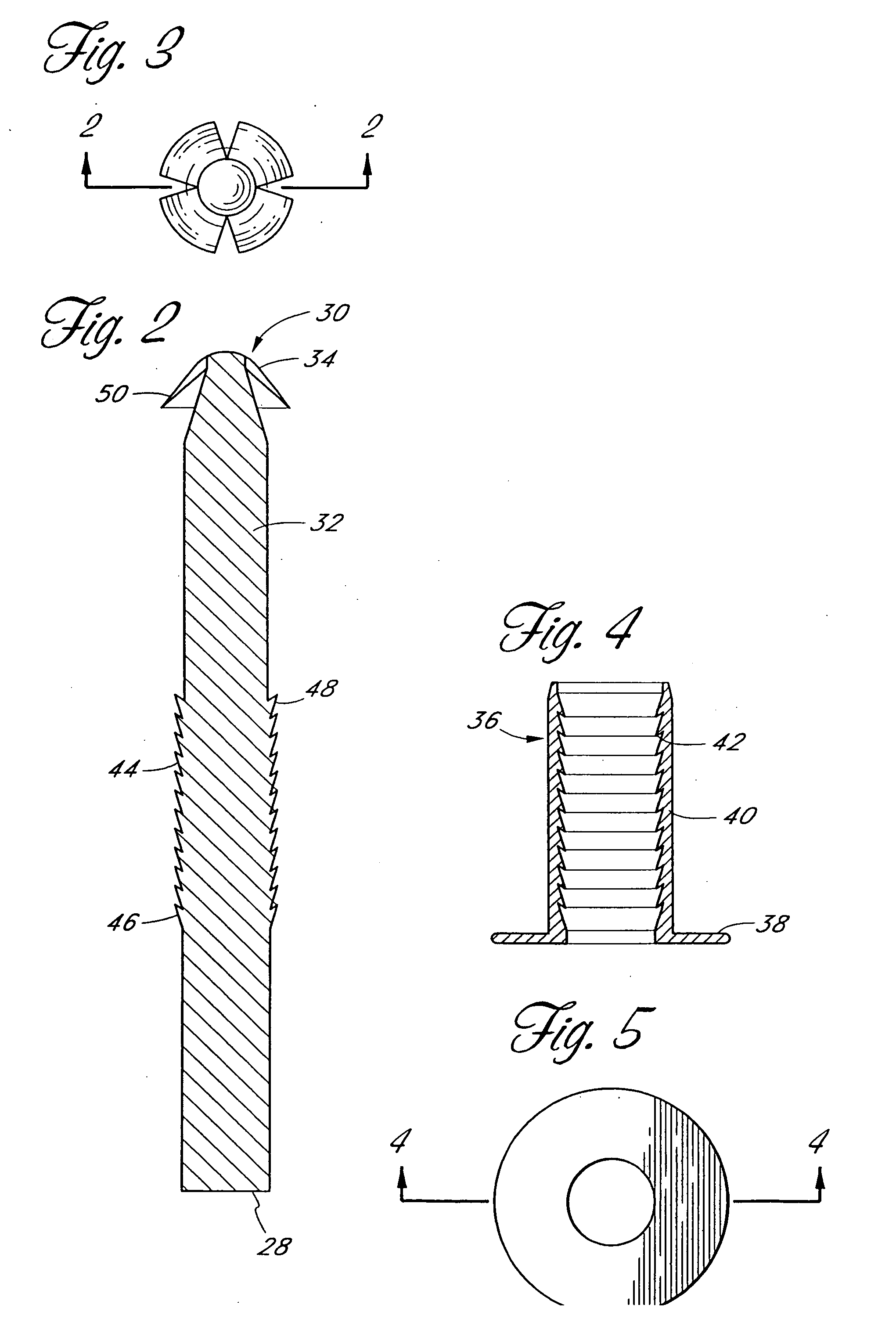
[0018] The distal end of the actuator may have a tapered surface, so that proximal retraction of the pin with respect to the actuator causes the anchor to incline outwardly as it slides along the tapered surface. The proximal end of the anchor may have a complementary tapered surface to slide along the tapered surface on the actuator. The pin may also have a relatively larger diameter near the distal end and a relatively smaller diameter proximally of the distal end.
[0019] In accordance with another aspect of the present invention, there is provided a bone fixation system for fixing two or more bone fragments. The fixation system comprises a first elongate tubular body, having a proximal end, a distal end and a longitudinal axis. A distal anchor is on the fixation device, moveable from a low profile orientation for distal insertion through a bore in the bone to an inclined orientation to resist axial proxi

Problems solved by technology

Notwithstanding the common use of the K-wire to achieve shear-force stabilization of bone fractures, K-wire fixation is attended by certain known risks.
Another potential complication involving the use of K-wires is in vivo migration.
Axial migration of K-wires has been reported to range from 0 mm to 20 mm, which can both increase the difficulty of pin removal as well as inflict trauma to adjacent tissue.
In addition to the undesirable appearance, percutaneously extending K-wires can be disrupted or cause damage to adjacent structures such as tendons if the K-wire comes into contact with external objects.

Method used


Image

  • Bone fixation system with radially extendable anchor
  • Bone fixation system with radially extendable anchor
  • Bone fixation system with radially extendable anchor

Examples


Embodiment Construction

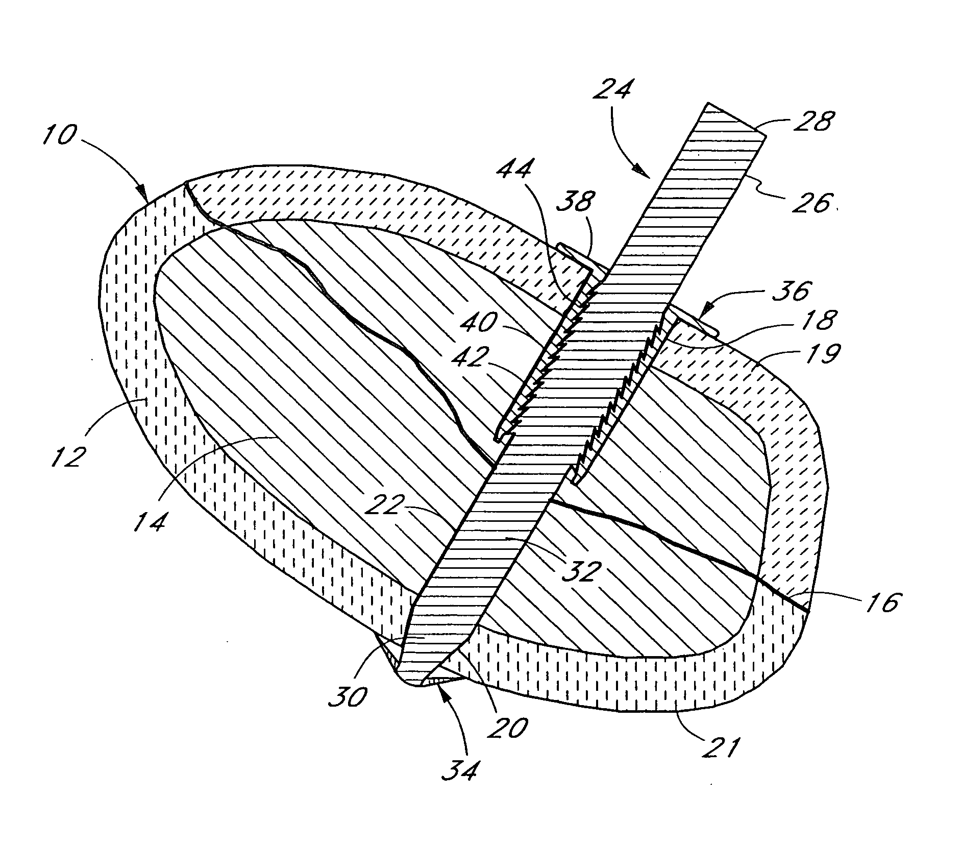
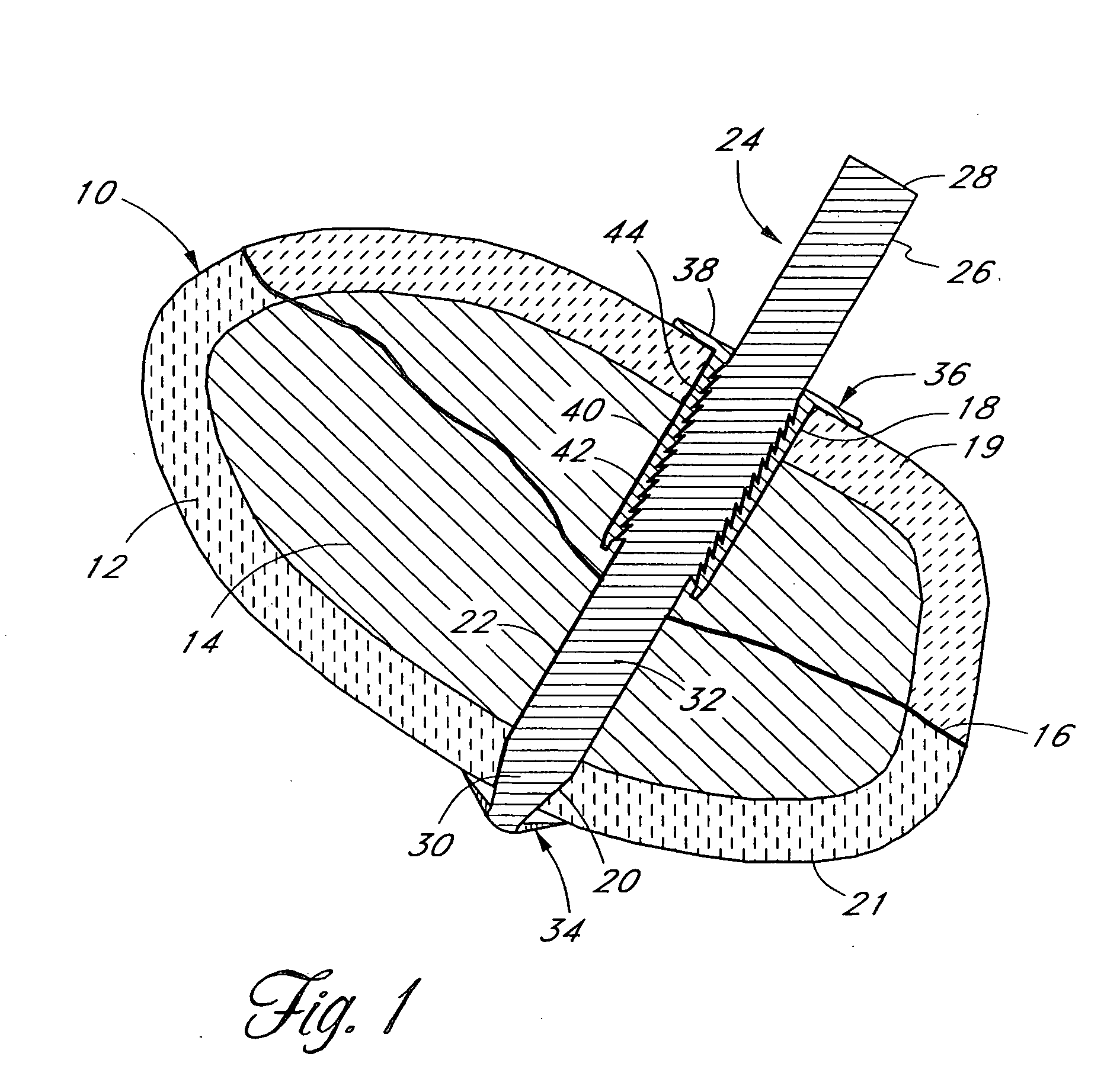
[0061] Although the application of the present invention will be disclosed in connection with the simplified bone fracture of FIG. 1, the methods and structures disclosed herein are intended for application in any of a wide variety of bones and fractures, as will be apparent to those of skill in the art in view of the disclosure herein. For example, the bone fixation device of the present invention is applicable in a wide variety of fractures and osteotomies in the hand, such as interphalangeal and metacarpophalangeal arthrodesis, transverse phalangeal and metacarpal fracture fixation, spiral phalangeal and metacarpal fracture fixation, oblique phalangeal and metacarpal fracture fixation, intercondylar phalangeal and metacarpal fracture fixation, phalangeal and metacarpal osteotomy fixation as well as others known in the art. A wide variety of phalangeal and metatarsal osteotomies and fractures of the foot may also be stabilized using the bone fixation device of the present inventio...


PUM


Abstract

Disclosed is a bone fixation device of the type useful for connecting soft tissue or tendon to bone or for connecting two or more bones or bone fragments together. The device comprises an elongate body having a distal anchor thereon, an actuator and a retention member. The retention member includes a proximal anchor that is axially movably disposed with respect to the distal anchor, to accommodate different bone dimensions and permit appropriate tensioning of the fixation device.

Description

RELATED APPLICATIONS [0001] This application claims the priority benefit under 35 U.S.C. § 119(e) of Provisional Application 60 / 440,828, filed Jan. 16, 2003 and is a continuation-in-part of Ser. No. 10 / 714,819, filed Nov. 17, 2003, which is a continuation of Ser. No. 09 / 832,289, filed Apr. 10, 2001 now U.S. Pat. No. 6,648,890, which is a continuation-in-part of Ser. No. 09 / 558,057, filed on Apr. 26, 2000, which is a continuation-in-part of Ser. No. 09 / 266,138 filed on Mar. 10, 1999 which is a divisional of Ser. No. 08 / 745,652 filed on Nov. 12, 1996, now U.S. Pat. No. 5,893,850.BACKGROUND OF THE INVENTION [0002] 1. Field of the Invention [0003] The present invention relates to bone fixation systems and, more particularly, absorbable or nonabsorbable bone fixation pins of the type for fixing soft tissue or tendons to bone or for securing two or more adjacent bone fragments or bones together. [0004] 2. Description of the Related Art [0005] Bones which have been fractured, either by acc...

Claims


Application Information

Patent Timeline
IPC IPC(8): A61B17/00A61B17/04A61B17/68A61B17/72A61B17/86A61F2/08
CPCA61B17/68A61B17/683A61B17/7266A61B17/7291A61B17/8685A61F2/0811A61B2017/0412A61B2017/0424A61B2017/0427A61B2017/0437A61B2017/0438A61B2017/00004
Inventor CACHIA, VICTOR V.CULBERT, BRAD S.WARREN, CHRISTOPHER
Owner TRIAGE MEDICAL
Learn More