
Automated control strategy for fuel processor reactor shift catalyst regeneration

a technology of automatic control strategy and fuel processor, which is applied in the direction of computer control, program control, instruments, etc., can solve the problems of decreasing the activity of the fuel processor with time, the inability to provide pure hydrogen as a natural resource, and the inability to provide such deposits of hydrogen

Inactive Publication Date: 2005-06-30
TEXACO INC
View PDF18 Cites 3 Cited by
  • Summary
  • Abstract
  • Description
  • Claims
  • Application Information

AI Technical Summary

Benefits of technology

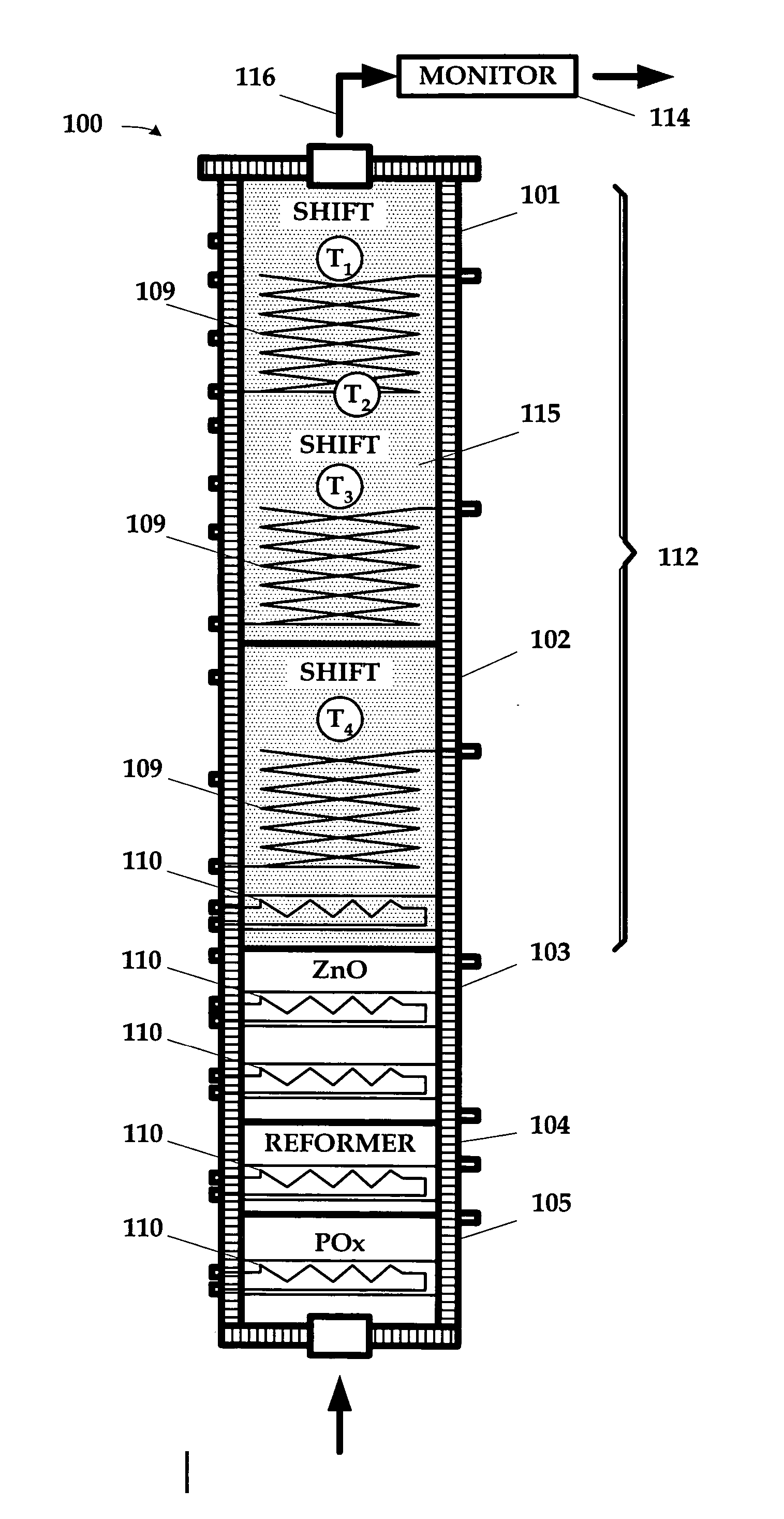
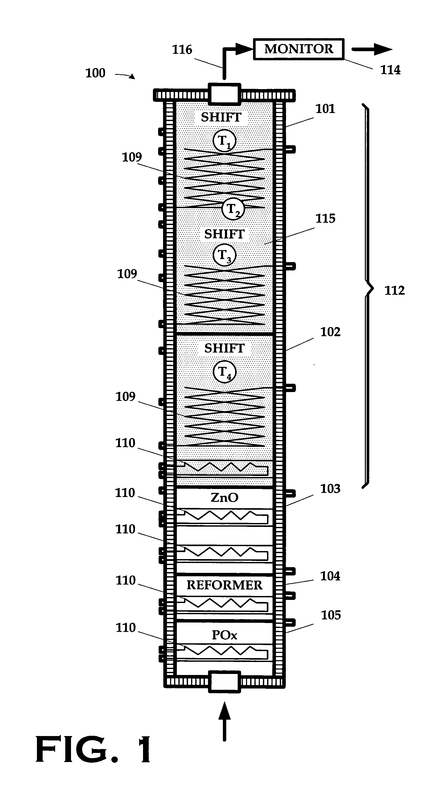
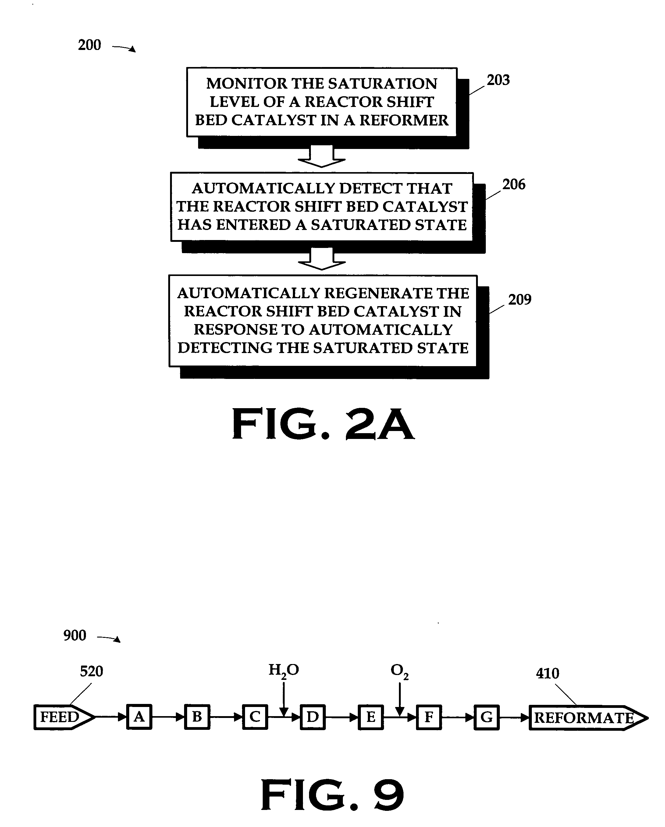
[0011] The invention includes, in its various aspects and embodiments, a method and apparatus for use in regenerating a reactor shift bed catalyst. In a first aspect, a method comprises monitoring the saturation level of a reactor shift bed catalyst in a reformer; automatically detecting that the reactor shift bed catalyst has entered a saturated state; and automatically regenerating the reactor shift bed catalyst in response to automatically detecting the saturated state. In a second aspect, a method comprises preparing the reformer for the automatic regeneration; purging the prepared reformer; heating a shift bed of the purged reformer; heating a preferential oxidizer of the purged reformer; actively controlling parameters of the regeneration; and resetting the reformer upon completing the regeneration. The apparatus may be, in various aspects, a program storage method encoded with instructions that, when executed by a computing device, performs such a method; a computing apparatus programmed to perform such a method, or a control system performing such a method.

Problems solved by technology

However, pure hydrogen is not available as a natural resource in a form that can be readily exploited.
Nature does not provide such deposits of hydrogen.
As a result, condensation sometimes occurs on the shift catalyst of the shift bed, thus decreasing its level of activity with time.
This decreasing level of activity negatively impacts the performance of the ATR.
Careful control of temperature across the catalyst bed during the regeneration is necessary yet difficult to control.
The task is tedious and arduous, and is compounded by the relatively long time that the process takes to complete.

Method used


Image

  • Automated control strategy for fuel processor reactor shift catalyst regeneration
  • Automated control strategy for fuel processor reactor shift catalyst regeneration
  • Automated control strategy for fuel processor reactor shift catalyst regeneration

Examples


Embodiment Construction

[0024] Illustrative embodiments of the invention are described below. In the interest of clarity, not all features of an actual implementation are described in this specification. It will of course be appreciated that in the development of any such actual embodiment, numerous implementation-specific decisions must be made to achieve the developers' specific goals, such as compliance with system-related and business-related constraints, which will vary from one implementation to another. Moreover, it will be appreciated that such a development effort, even if complex and time-consuming, would be a routine undertaking for those of ordinary skill in the art having the benefit of this disclosure.

[0025] The present invention is generally directed to method and apparatus for controlling the reaction temperature of a “fuel processor,” or “reformer,” i.e., an apparatus for converting hydrocarbon fuel into a hydrogen rich gas. The term “fuel processor” shall be used herein. In the embodimen...


PUM

PropertyMeasurementUnit
temperatureaaaaaaaaaa
operating temperatureaaaaaaaaaa
temperatureaaaaaaaaaa

Abstract

A method and apparatus for use in regenerating a reactor shift bed catalyst are disclosed. The method comprises monitoring the saturation level of a reactor shift bed catalyst in a reformer; automatically detecting that the reactor shift bed catalyst has entered a saturated state; and automatically regenerating the reactor shift bed catalyst in response to automatically detecting the saturated state. The apparatus may be, in various aspects, a program storage method encoded with instructions that, when executed by a computing device, performs such a method; a computing apparatus programmed to perform such a method, or a control system performing such a method.

Description

[0001] This is a continuation-in-part of co-pending U.S. application Ser. No. 10 / 407,488, entitled “Architectural Hierarchy of Control for a Fuel Processor,” filed Apr. 19, 2003, in the name of the inventors Vesna R. Mirkovic et al., and commonly assigned herewith.BACKGROUND OF THE INVENTION [0002] 1. Field of the Invention [0003] The present invention is directed to a fuel processor, and, more particularly, to a control system for use in a fuel processor. [0004] 2. Description of the Related Art [0005] There are numerous uses for pure hydrogen or hydrogen-enriched gas streams. For instance, fuel cells—a promising alternative energy source-typically employ hydrogen as a fuel for generating power. Many industrial processes also employ hydrogen or hydrogen-enriched gas streams in a variety of fields for the manufacture and production of a wide assortment of end products. However, pure hydrogen is not available as a natural resource in a form that can be readily exploited. As an exampl...

Claims


Application Information

Patent Timeline
Patent Type & Authority Applications(United States)
IPC IPC(8): G05B19/042H01M8/04H01M8/06
CPCG05B19/0421G05B2219/2208G05B2219/2668H01M8/04223H01M8/04992Y10T436/11H01M8/0662Y02E60/50Y10T436/115831Y10T436/12H01M8/0612H01M8/04303H01M8/04228G05B21/00G05B13/02G05B15/00H01M8/04302H01M8/04225
Inventor SUN, HONGQIAOCASEY, DANIEL G.MIRKOVIC, VESNA R.BALASUBRAMANIAN, BHASKARWHEAT, W. SPENCERKRAUSE, CURTIS L.
Owner TEXACO INC
Learn More