Vacuum cleaner attachment and method of use thereof

Inactive Publication Date: 2005-07-07
EVERGREEN WORKS
View PDF17 Cites 6 Cited by
  • Summary
  • Abstract
  • Description
  • Claims
  • Application Information

AI Technical Summary

Benefits of technology

[0011] Another feature and advantage of the present invention is its unique combination and configuration of flexible cleaning elements that permit maximum airflow into the vacuum cleaner attachment, thereby enhancing cleaning performance.
[0012] Another feature and advantage of the present invention is its ability to prevent the occurrence of unsightly streaks, runs and/or spots.
[0013] Another feature and advantage of the present invention is its ability to effectively and effi

Problems solved by technology

This conventional method requires substantial physical exertion by the operator to scrub and wring out the cleaning head.
Moreover, dirty solution is repeatedly placed back onto the cleaning surface, resulting in an ineffective cleaning method.
Nevertheless, many of these cleaning attachments are inefficient, messy, and still require a significant amount of operator effort.
Some of these cleaning attachments are relatively efficient when utilized on flat and uniform surfaces that are readily accessible; however, they are relatively ineffective and provide unsatisfactory results when the surface to be cleaned is curved, uneven or is located in a relatively restricted area.
In the car detailing industr

Method used


Image

  • Vacuum cleaner attachment and method of use thereof
  • Vacuum cleaner attachment and method of use thereof
  • Vacuum cleaner attachment and method of use thereof

Examples


Embodiment Construction

[0023] In describing the preferred and selected alternate embodiments of the present invention, as illustrated in FIGS. 1-6, specific terminology is employed for the sake of clarity. The invention, however, is not intended to be limited to the specific terminology so selected, and it is to be understood that each specific element includes all technical equivalents that operate in a similar manner to accomplish similar functions.

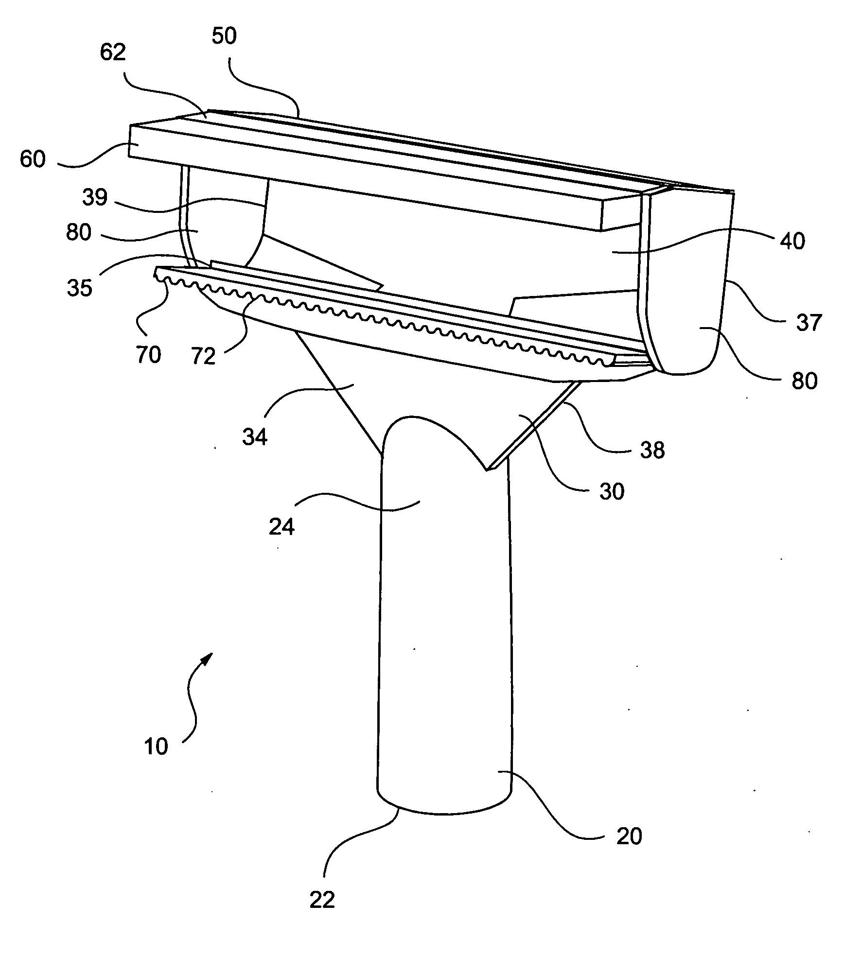
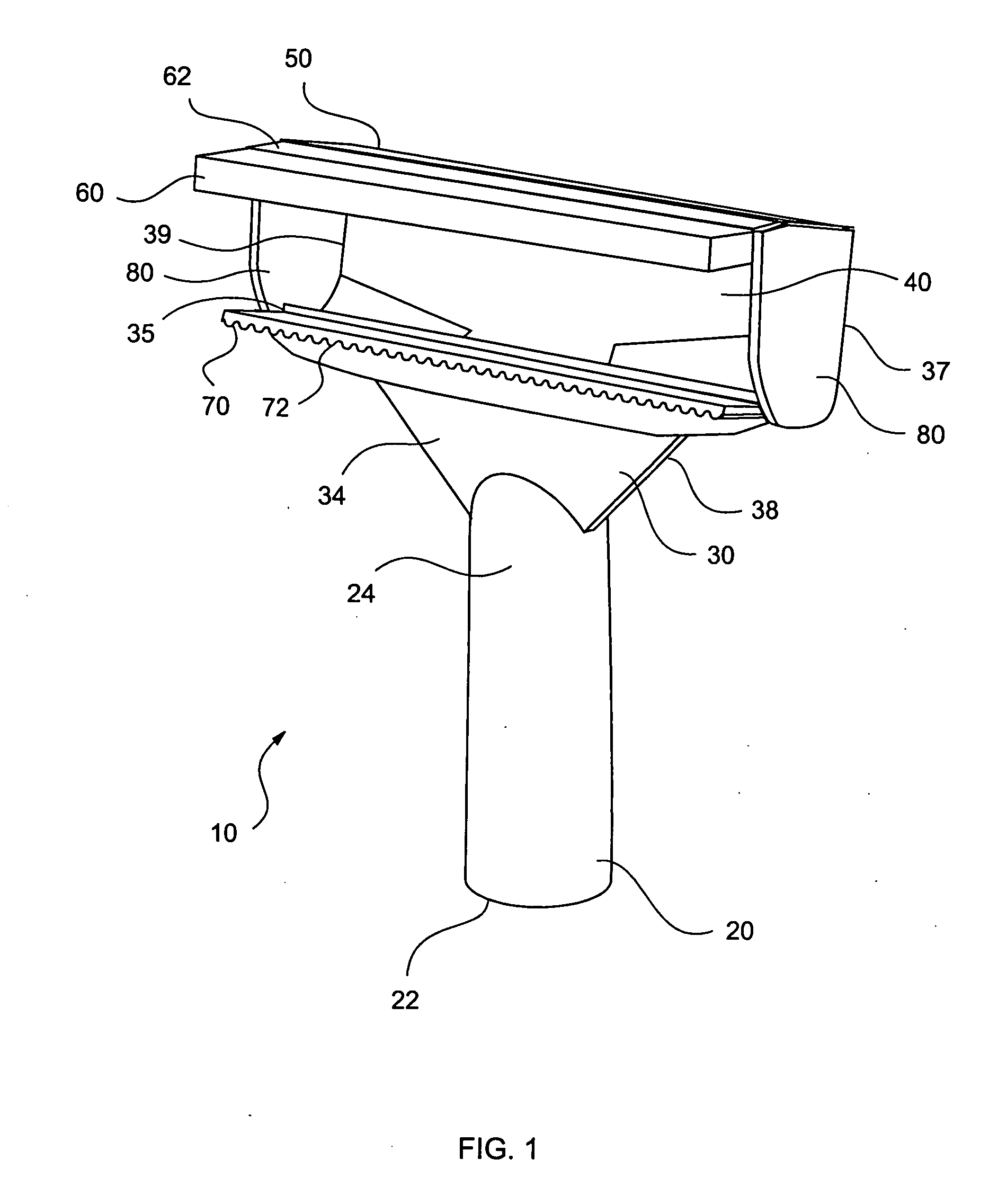
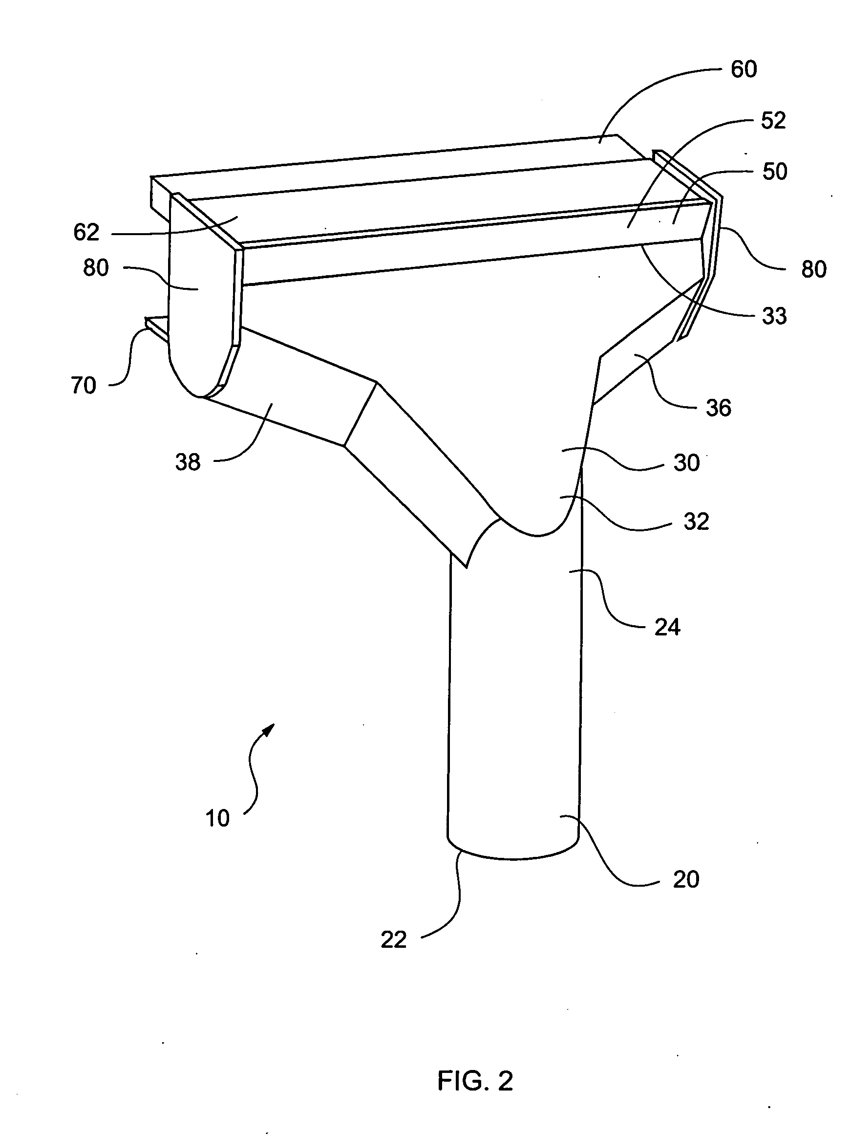
[0024] Referring now to FIGS. 1-2, the present invention in a preferred embodiment is a vacuum cleaner attachment 10 generally preferably possessing handle 20, head 30, semi-absorbent pad 60, squeegee 70, and sidewalls 80. Preferably, handle 20 is a cylindrical tube having first end 22 and second end 24, wherein first end 22 is dimensioned to receive a vacuum hose, thereby removably attaching vacuum cleaner attachment 10 to a vacuum cleaner. Although it is preferred that vacuum cleaner attachment 10 be attached to the vacuum cleaner by frictional fit, it is ...


PUM


Abstract

A vacuum cleaner attachment, especially suited for a wet/dry vacuum cleaner, having a ridged squeegee, a semi-absorbent pad and sidewalls for efficiently and effectively removing liquid and debris from a cleaning surface. The unique combination and orientation of cleaning elements permit maximum airflow into the cleaning attachment, thereby improving cleaning performance.

Description

TECHNICAL FIELD [0001] The present invention relates generally to vacuum cleaner attachments, and more specifically to a cleaning attachment especially suited for a wet / dry vacuum cleaner, having a squeegee, a semi-absorbent pad and sidewalls, wherein the unique combination and orientation of cleaning elements permit maximum air flow into the cleaning attachment, thereby improving cleaning performance. BACKGROUND OF THE INVENTION [0002] Various methods are known for cleaning surfaces. The method selected depends on whether it is desired to remove loose debris lying on a surface to be cleaned, in which a vacuum device or a brush and pan are utilized, or whether it is desired to remove water soluble material and / or very fine loose material from the surface. In the latter case, a sponge and / or mop, accompanied by water, is typically utilized. In a typical manual method for removing water soluble material and fine dust, a cleaning head is attached to a handle, which is dipped into a buc...

Claims


Application Information

Patent Timeline
IPC IPC(8): A47L7/00A47L9/06
CPCA47L7/0009A47L9/0673A47L9/0613A47L9/06
Inventor YOU, JUNGSHIN, CHAE WONSHINN, YOUNG KYO
Owner EVERGREEN WORKS
Why Eureka
Try Eureka