Flower container

Inactive Publication Date: 2005-07-07
RDS INNOVATIONS
17 Cites 2 Cited by

AI-Extracted Technical Summary

Problems solved by technology

These flower bunches are often difficult to carry along with other shopping articles and bags.
While juggling with several shopping items, a busy shopper often accidentally damages the delicate flowers.
Another drawback of the traditional flower envelope is that they are designed for a ...

Benefits of technology

[0009] A further object of the invention is to provide a container which prevents the flowers from being accidentally damaged during transportation.
[0010] The invention will also prov...

Abstract

A container adapted for carrying long stemmed flowers includes a sheet of inherently flexible material which defines a receptacle having an aperture at its top section facilitating the insertion or removal of the flowers and a wall enveloping the flowers when they are placed in the receptacle and which tapers from top to bottom. The bottom region is of sufficiently small cross-section in order to retain the flowers when they are placed in the receptacle. The wall is adapted to receive—or itself incorporating—one or more shoulder straps long enough to enable a user of the container to carry it, in use, on his or her shoulder and/or generally diagonally across his or her back.

Application Domain

Travelling sacksTravelling carriers +6

Technology Topic

EngineeringMechanical engineering

Image

  • Flower container
  • Flower container
  • Flower container

Examples

  • Experimental program(1)

Example

DETAILED DESCRIPTION OF THE DRAWINGS
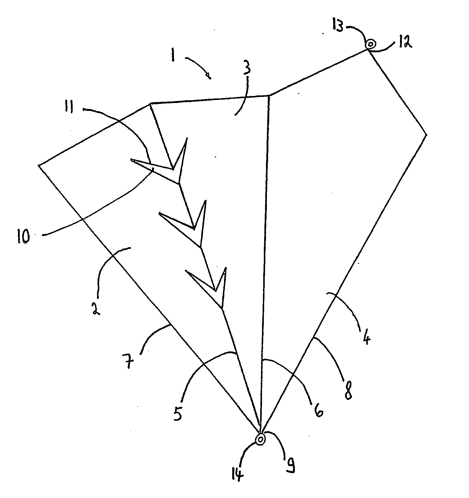
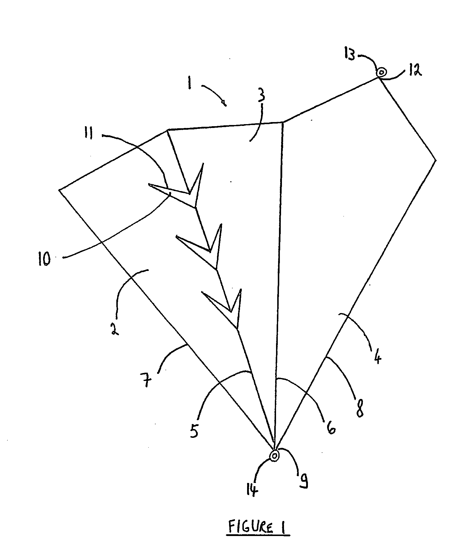
[0034]FIG. 1 shows an unfolded sheet 1 which is sectioned into three portions 2, 3 and 4 by two fold lines 5 and 6 which extend from the top edge of the sheet and which converge with side edges 7 and 8 at point 9 of the sheet 1.
[0035] Fold line 5 is interrupted at regular intervals by three V-shaped cut-outs 10 whose edges 11 extend at an angle comprised between 30° and 50° from the fold line. The person skilled in the art will select an appropriate number of cut-outs to meet his requirements of flexibility for a given container.
[0036] Portion 4 of the sheet 1 is the surface which is designated to run against the back and/or shoulder of the user. This portion projects beyond the length of the other two portions 2 and 3 in the shape of a triangle whose edges converge at a higher extremity 12.
[0037] A first ring 13 is attached to sheet 1 at point 12 of the sheet by any appropriate method selected by the person skilled in the art from any known alternatives. A second ring 14 is attached in a similar manner at point 9 of sheet 1.
[0038] A strap which is not represented on the figure can easily be assembled to rings 13 and 14.
[0039]FIG. 2 presents a container 21 which is the result of folding the sheet 1 presented in FIG. 1 and attaching edges 7 and 8 together. In this configuration fold line 25 separates faces 23 and 22 of the container 21. And portion 4 of FIG. 1 has become face 24. Thus, faces 23, 22 and 24 are the walls of a container into which flowers may be easily inserted, removed and carried from one location to the next.
[0040]FIG. 3 shows a container 31 in which face 34 is curved in order to conform to the shape of the user's back and/or shoulder. This flower container or flower quiver incorporates as did sheet 1 and container 21, three cut-outs which allow the container to flex in any direction without the wall of the container tearing.
[0041] In FIGS. 4A and 4B, sheet 41 and container 42 are illustrated with a separable base 43. The base 43 is of the type that can be simply slid into container 42 and held therein by simple friction at its lower extremity. This base can interact with the wall of the container in such a manner as to prevent the passage of water from the inside of the container to the outside.
[0042] The base can be made of any appropriate material—the user may for example if he wishes select a porous base in order to absorb and retain liquid which could hydrate the flowers during transportation.
[0043] The incorporation of the base element will also permit the lower cross-section of the container to be larger than the lower cross-section of the containers represented in the previous drawings. This will enable the user to place a large amount of flowers in the container or to place therein flowers whose size would require the container to have a large base.
[0044] The base section may also be secured to the sheet or wall of the container by other methods than the friction between the base and the wall. A loop and hook attachment, for example, may be provided to fix the base to the wall of the container.
[0045]FIG. 4A also shows two parallel slits 44 and 45 which form the strap 46 for the carrying of the container.
[0046] Furthermore, the sheet 41 comprises projections 48 which can easily be inserted into the rectangular cut-outs 47 to releasebly attach the edges of the sheet. The person skilled in the art will easily be able to determine alternative means of releasable attachments such as push buttons and zips.
[0047]FIG. 5 shows a sheet 50 prior to being folded into a container. Sheet 50 comprises in its lower region a ring 51 attached to the main body 52 of sheet 50 by known attachment means. Ring 51 may also be made integral to the main body 52 of sheet 50 in order to simplify the manufacturing process required to produce the inventive sheet.
[0048] In the upper region of the sheet, lid 53 is provided which incorporates a projection 54 whose geometry is so selected by the person skilled in the art to allow it to be matingly engaged to cut-out 55 located in the upper region of the main body 52 of sheet 50. There is also provided in said upper region ring 56 whose properties allow the engagement of a strap for carrying the container which the sheet 50 may be formed into.

PUM

no PUM

Description & Claims & Application Information

We can also present the details of the Description, Claims and Application information to help users get a comprehensive understanding of the technical details of the patent, such as background art, summary of invention, brief description of drawings, description of embodiments, and other original content. On the other hand, users can also determine the specific scope of protection of the technology through the list of claims; as well as understand the changes in the life cycle of the technology with the presentation of the patent timeline. Login to view more.

Similar technology patents

Air-conditioner for vehicles

InactiveUS20050092479A1secure spaceprevent be damage
Owner:DENSO CORP

Golf course flag retention device

InactiveUS6939239B1prevent be damage
Owner:ASH KEVIN C

Classification and recommendation of technical efficacy words

  • prevent be damage
  • prevent dehydration

Method of manufacturing an electro-optical device

InactiveUS6465268B2prevent be damagehigh integration density
Owner:SEMICON ENERGY LAB CO LTD

End-effector force measurement drive circuit

ActiveUS20150316431A1prevent be damage
Owner:TYCO HEALTHCARE GRP LP

Electronic fabric and preparing thereof

InactiveUS20100206614A1prevent be damageretain function
Owner:KOLON GLOTECH INC

Touch panel and touch display device using the same

InactiveUS20120075218A1prevent be damage
Owner:WINTEK TECH DONGGUAN +1

Jujube tree grafting method

InactiveCN103070025Aprevent dehydrationquality improvement
Owner:XINJIANG ACADEMY OF AGRI & RECLAMATION SCI

Clysis fluid for infantile diarrhea caused by damp-heat

InactiveCN103656337Aprevent dehydrationAvoid subtraction
Owner:刘黎明

Fresh-keeping basket with automatic waxberry cleaning function and use method of fresh-keeping basket

PendingCN114435728Aprevent dehydrationImprove freshness preservation performance
Owner:靖州县中山杨梅科技有限责任公司
Why Eureka
Try Eureka