Locking structure for protector and wire harness

a technology of locking structure and protector, which is applied in the direction of insulated conductors, cables, conductors, etc., can solve the problems of increasing production costs, protectors 100/b> may be twisted, and backlash may occur, so as to prevent protector twisting, and eliminate backlash of locking parts

Active Publication Date: 2005-07-07
YAZAKI CORP
View PDF12 Cites 30 Cited by
  • Summary
  • Abstract
  • Description
  • Claims
  • Application Information

AI Technical Summary

Benefits of technology

[0022] In the wire harness having the above described structure, the backlash preventive locking parts are appropriately provided, in place of the locking parts, on the protector which is mounted on the wire harness. Therefore, backlashes of the locking parts can be eliminated, and a twist of the protector can be prevented. In this manner, determined parts of the wire harness can be reliably protected.
[0023] According to the invention, backlashes of the locking parts can be eliminated by a simple structure, and a twist of the protector can be prevented.

Problems solved by technology

Therefore, there has been a problem that a backlash may occur, and the protector 100 may be twisted.
However, in order to provide the latching projections 114 on the inner faces of the latched part 111, a complicated mold has been required, which has led to such an inconvenience that a rise of the production cost has been inevitable.

Method used


Image

  • Locking structure for protector and wire harness
  • Locking structure for protector and wire harness
  • Locking structure for protector and wire harness

Examples


Embodiment Construction

[0033] Now, embodiments according to the invention will be described referring to the drawings.

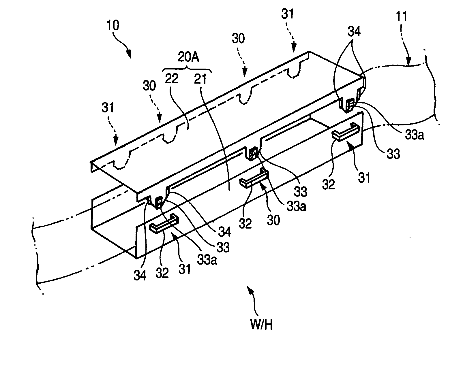
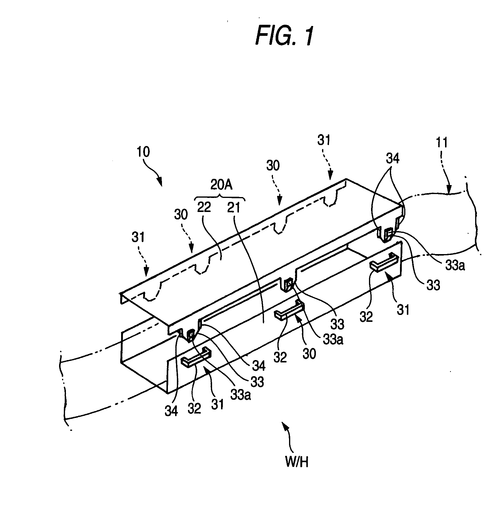
[0034] As shown in FIG. 1, in a locking structure 10 for a protector according to the invention, a protector 20A which is a tubular body formed by assembling a main body 21 and a cover 22 together so as to contain a bundle 11 of electric wires, is provided with a plurality of locking parts 30 which can engage the main body 21 and the cover 22 with each other. These locking parts 30 are arranged on the main body and the cover 22 at a determined interval in a longitudinal direction thereof (in a direction from left to right in FIG. 1), and at least two of the locking parts 30 are formed as backlash preventive locking parts 31.

[0035] For example, in the protector 20A as shown in FIG. 1, at both sides (upper and lower sides in FIG. 1) of the protector 20A which is a rectilinear tubular body, the backlash preventive locking parts 31 are arranged at opposite end parts in the longitudinal direc...


PUM

PropertyMeasurementUnit
locking structureaaaaaaaaaa
thicknessaaaaaaaaaa
widthaaaaaaaaaa

Abstract

A bundle 11 of electric wires is contained in a protector 20 which is a tubular body formed by assembling a main body 21 and a cover 22 together, and the main body 21 and the cover 22 are fixed to each other by means of locking parts 30. On this occasion, backlash preventive locking parts 31 each having backlash preventing means 34 are arranged in at least two positions, in place of the locking parts 30 which are arranged on the main body 21 and the cover 22 at a determined interval in a longitudinal direction. As the results, backlashes of the locking parts can be eliminated by a simple structure, and a twist of the protector can be prevented.

Description

BACKGROUND OF THE INVENTION [0001] 1. Field of the Invention [0002] The present invention relates to a locking structure for a protector and a wire harness, and more particularly, to the locking structure for the protector for protecting the wire harness which is arranged, for example, in an automobile, and the wire harness itself. [0003] 2. Related Art [0004] As a conventional locking structure for a protector and a wire harness, such a structure as shown in FIGS. 6 and 7 has been known. As shown in FIG. 6, a protector 100 in a form of a tubular body includes a main body 101 and a cover 102 which can be assembled together so as to contain a bundle 103 of electric wires. A plurality of locking parts 110 for enabling the main body 101 and the cover 102 to be engaged with each other are provided between this main body 101 and the cover 102. [0005] As shown in FIG. 7, each of the locking parts 110 includes a latched part 111 in a gate-like shape having a space 111a inside, which is pro...

Claims


Application Information

Patent Timeline
Patent Type & Authority Applications(United States)
IPC IPC(8): H05K7/00B60R16/02H01B7/00H02G3/04
CPCH02G3/0418B60R16/0215
Inventor DAITO, KOJI
Owner YAZAKI CORP
Why Eureka
Try Eureka