

Center buffer coupling for railroad cars
a technology for center buffer coupling and railroad cars, which is applied in the direction of railway couplings, slip couplings, railway components, etc., can solve the problem of losing its function as a connecting elemen
- Summary
- Abstract
- Description
- Claims
- Application Information
AI Technical Summary
Benefits of technology
Problems solved by technology
Method used
Image

Examples
Embodiment Construction
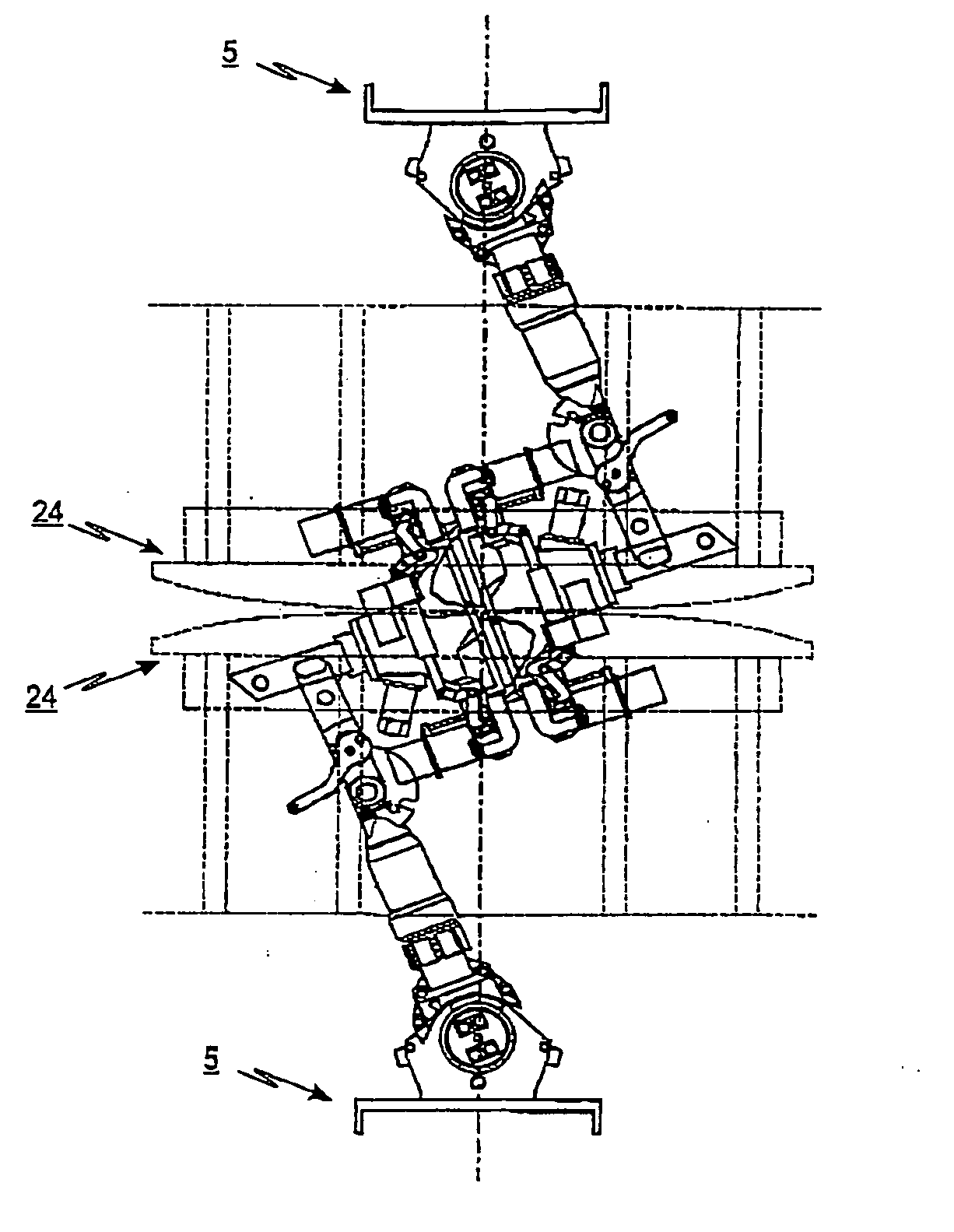
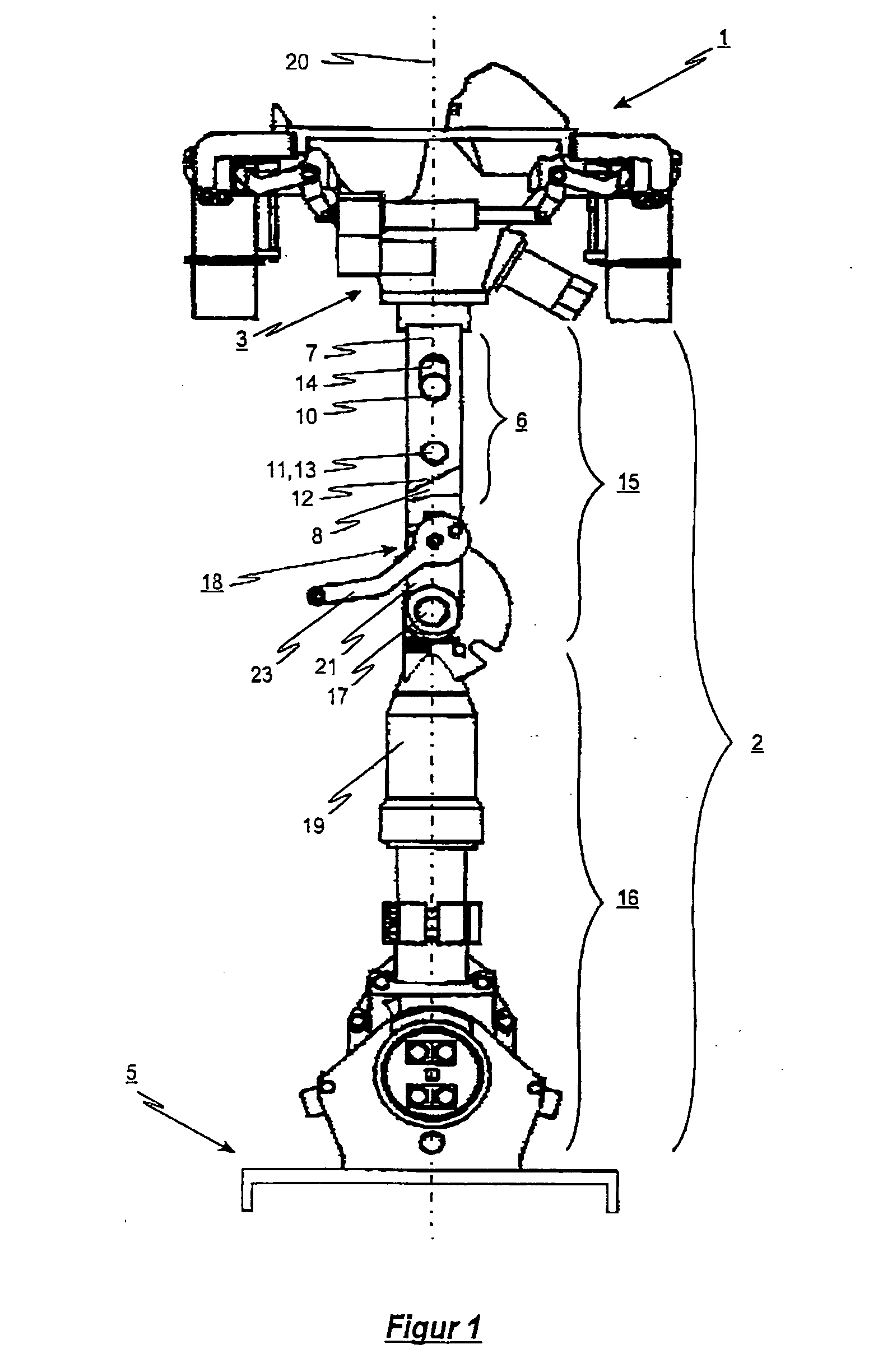
[0029]FIG. 1 shows a preferred embodiment of the center buffer coupling according to the invention in uncoupled and extended state. The coupling shaft 2 of the center buffer coupling consists of a front shaft part 15 that holds the coupling head 1 on its front end 3 and a rear shaft part 16 that is hinged to the subframe and / or frame 5 of the railroad car so that it can swivel horizontally. The front shaft part 15 is designed on its free end as a clevis with upper and lower fork shanks, whereby the fork shanks hold the rear shaft part 16 between them. By means of a connecting bolt 17 between clevis and shaft part 16, the front shaft part 15 and the rear shaft part 16 are connected to each other in such a way that the front shaft part 15 can swivel horizontally with respect to the rear shaft part 16.
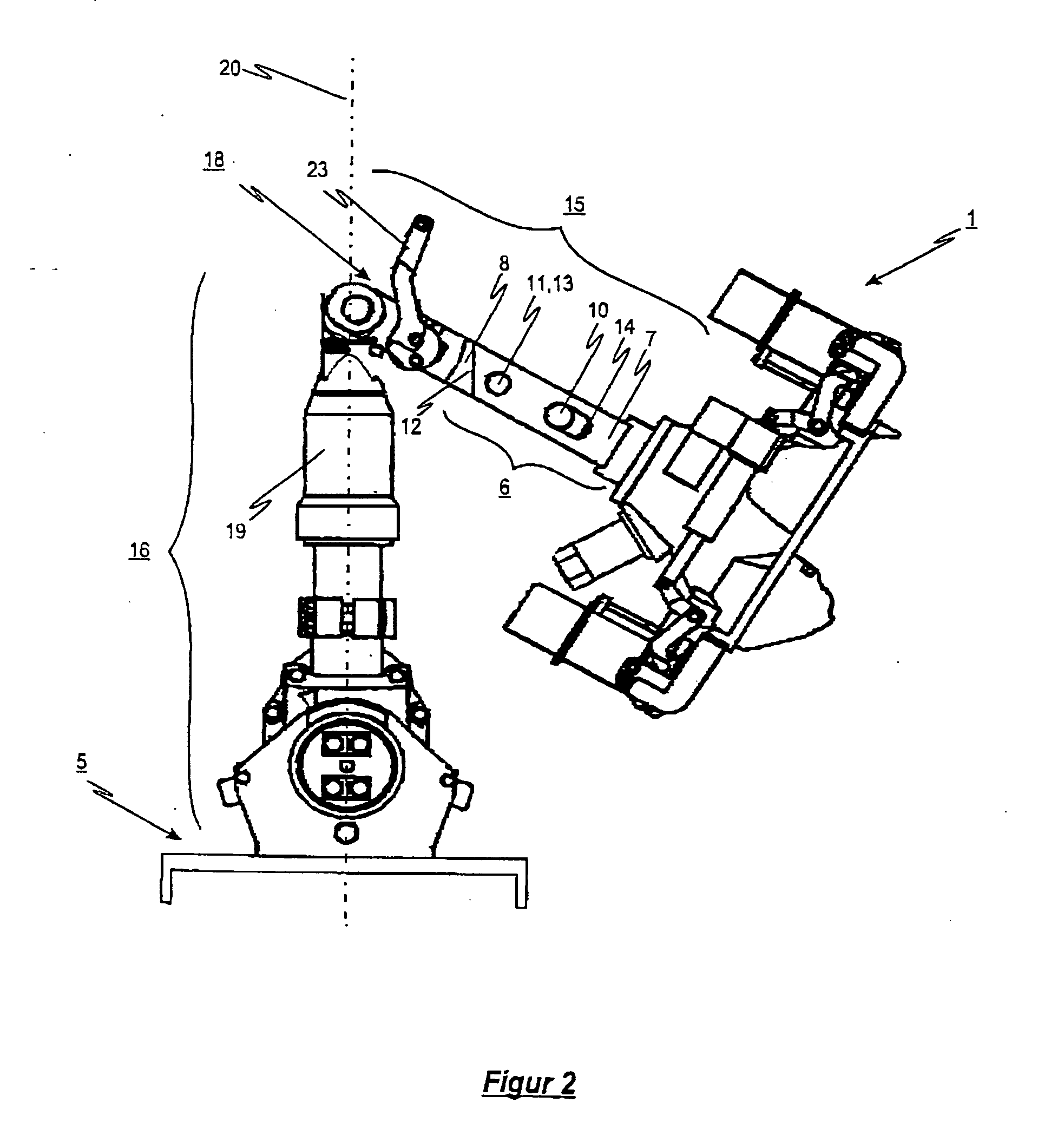
[0030]FIG. 2 shows the center buffer coupling according to FIG. 1 in uncoupled and swiveled state. The reference number 18 designates a locking device that permits locking, free of play,...
PUM
 Abstract
Description
Claims
Application Information