Transmit receive switch with high power protection

Inactive Publication Date: 2005-07-07
OPTIS WIRELESS TECH LLC
View PDF3 Cites 18 Cited by
  • Summary
  • Abstract
  • Description
  • Claims
  • Application Information

AI Technical Summary

Benefits of technology

[0009] The invention seeks to accomplish a microwave switch for switching between incoming signals from an antenna and outgoing signals to

Problems solved by technology

However, circulators are only effective up to certain magnitudes of power.
Another drawback with ferrite c

Method used


Image

  • Transmit receive switch with high power protection
  • Transmit receive switch with high power protection
  • Transmit receive switch with high power protection

Examples


Embodiment Construction

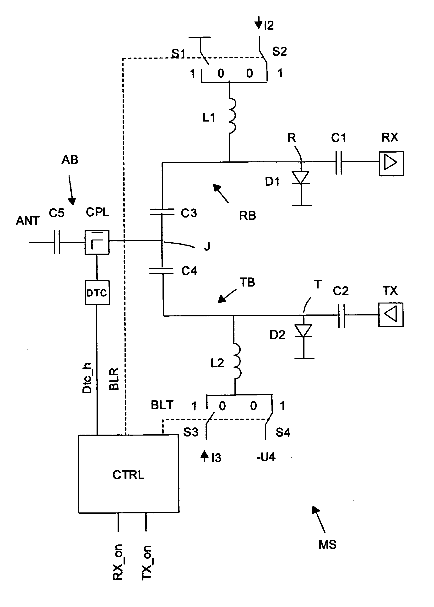
[0025] In FIG. 1, a first embodiment of the microwave switch apparatus according to the invention has been shown.

[0026] The microwave switching apparatus MS comprises an antenna terminal ANT, which is adapted to be coupled to an external antenna (not shown). The microwave switching apparatus is also adapted to be coupled to a radar system (not shown), which controls the switching apparatus. The antenna terminal is being coupled over an optional capacitor C5 to an antenna branch AB, which is connected to a first junction J. The antenna branch may advantageously comprise a coupler CPL. The first junction J couples to a receive branch RB and a transmit branch TB.

[0027] The first junction J connects to first receive branch capacitor C3, which couples to a receive branch RB comprising a receive junction R. The receive branch RB couples to a second receive branch capacitor C1 coupling to a receive amplifier RX. The receive junction R is preferably arranged at a distance corresponding to...


PUM


Abstract

Microwave switch (MS) comprising an antenna branch (AB), a receive branch (RB), and a transmit branch (TB). According to one embodiment, the switch comprises a protection circuit (CPL, DTC, CTRL), which upon a high power signal (Dtc_h) being present on the antenna branch effectuates a biasing of semiconductors on both the receive branch (RB) and the transmit branch (TB). According to one embodiment PIN diodes are provided for controlling switching between the transmit and the receiv branch as well as enabling a protective mode, the control being accomplished by selectively biasing respective diodes.

Description

FIELD OF THE INVENTION [0001] The present invention relates to a switch arrangement for a microwave transmit and receive system. More particularly the invention relates to a switch and protection arrangement for a transmit and receive system and in particular a radar system. BACKGROUND OF THE INVENTION [0002] In typical synthetic aperture radar systems a plurality of antenna elements are provided, through which both high power signals are emitted and corresponding low power echoes are received. So-called transmit receive (T / R) modules have the function of switching between incoming and outgoing signals and to provide input and output phase adjustment as well as input amplification. [0003] It is widely known to use ferrite circulators in order to separate incoming and outgoing signals. However, circulators are only effective up to certain magnitudes of power. [0004] Another drawback with ferrite circulators is their bulk and weight. [0005] It is known to use passive limiters for prot...

Claims


Application Information

Patent Timeline
IPC IPC(8): G01S7/03H04B1/48
CPCG01S7/032H04B1/48G01S7/034
Inventor KARLSSON, PETEREMANUELSSON, THOMAS OVE
Owner OPTIS WIRELESS TECH LLC
Why Eureka
Try Eureka