
Signal transmit-receive switching radio frequency amplifier for wireless communication system

A technology for wireless communication systems and radio frequency amplifiers, applied in high-frequency amplifiers, transmission systems, electrical components, etc., can solve the problems of inconvenient installation, poor heat dissipation, and high price, and achieve low insertion loss, simple structure, and low cost. Effect

Active Publication Date: 2010-12-01
上海金网通信技术发展有限公司
View PDF4 Cites 0 Cited by
  • Summary
  • Abstract
  • Description
  • Claims
  • Application Information

AI Technical Summary

Problems solved by technology

In this case, it is difficult to increase the power. In the case of output power greater than 10W
In practical applications, often due to no-load or poor standing wave of the antenna, the power reflection often burns the communication equipment, paralyzes the communication system and requires considerable maintenance costs
Especially in the MiWAVE broadband wireless emergency communication system, the use environment is very harsh and complex, and the equipment is more likely to be damaged
[0003] The power of the existing coaxial radio frequency mechanical switch can be greater than 10W, but the switching speed is at the ms level, the switching speed cannot meet the requirements, and the volume is large, it is not easy to install, and the price is expensive
IC chip switches are fast and small in size, but they can withstand very little power, have poor heat dissipation, and are easy to break

Method used


Image

  • Signal transmit-receive switching radio frequency amplifier for wireless communication system
  • Signal transmit-receive switching radio frequency amplifier for wireless communication system

Examples


Embodiment Construction

[0011] The present invention will be further described below in conjunction with accompanying drawing.

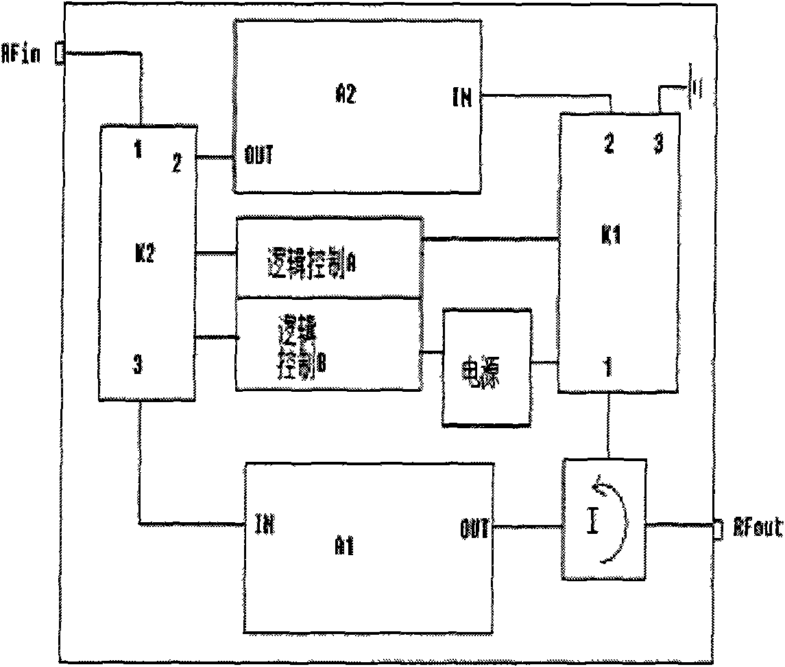
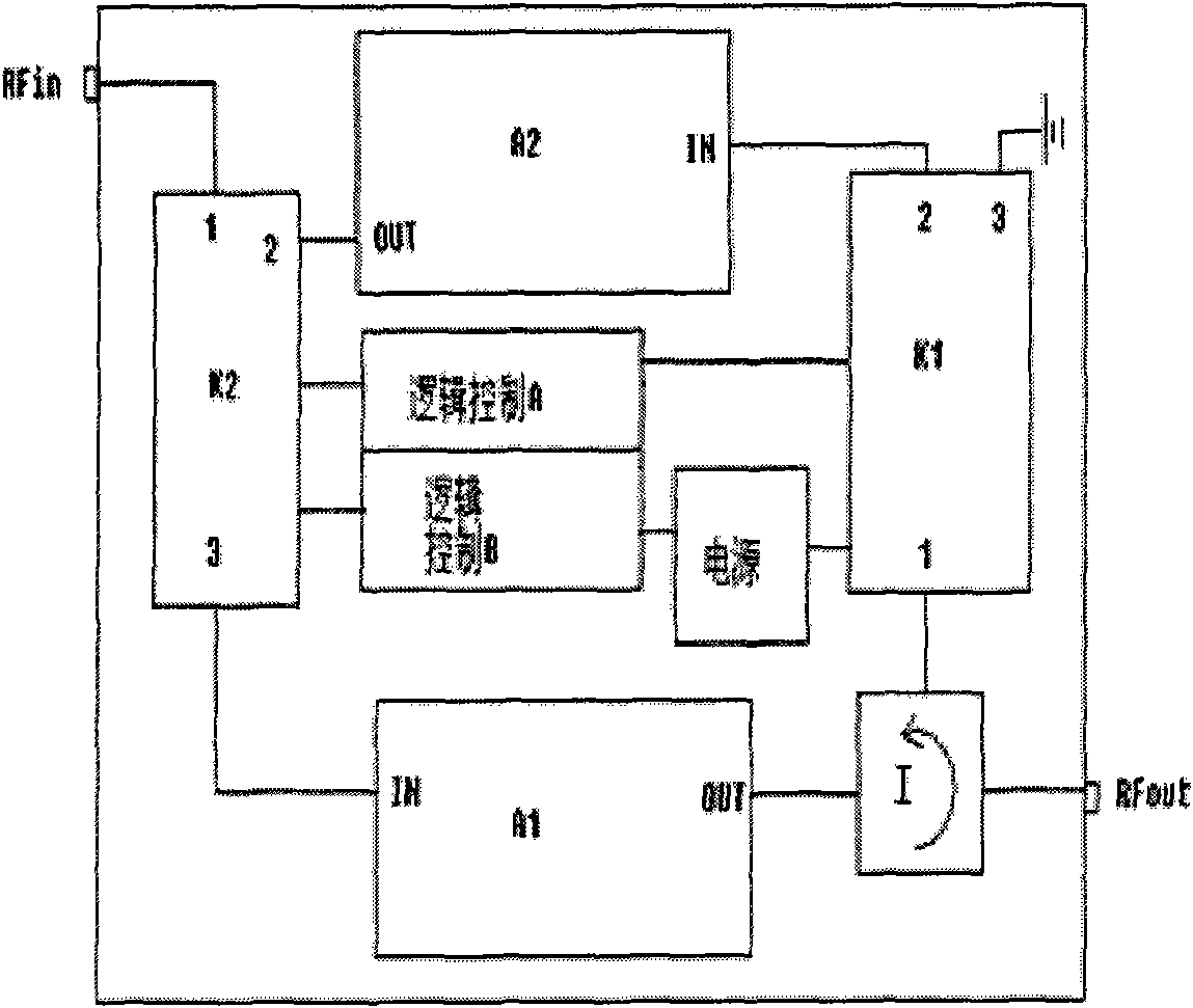
[0012] Such as figure 1 As shown, a signal transceiving and switching radio frequency amplifier for a wireless communication system includes a signal transmitting module F, a signal receiving module R, a logic control module A, a logic control module B, a radio frequency switch module K1, a radio frequency switch module K2, and an RFin port , RFout port, circulator I and power supply, the input end of described signal transmitting module F is connected with the output end of RFin port and signal receiving module R through radio frequency switch module K2, the output end of described signal transmitting module R is through Circulator I is connected with RFout port and radio frequency switch module K2, the input end of described signal receiving module R is connected with radio frequency switch module K1, and described logic control module A, logic control module B are all co...


PUM


Abstract

The invention relates to a signal transmit-receive switching radio frequency amplifier for a wireless communication system. The amplifier is characterized by comprising a signal transmitting module F, a signal receiving module R, a logic control module A, a logic control module B, a radio frequency switch module K1, a radio frequency switch module K2, an RFin port, an RFout port, a circulator I and a power supply source, wherein the input end of the signal transmission module F is connected with the RFin port and the output end of the signal receiving module R through the radio frequency switch module K2; the output end of the signal transmitting module R is connected with the RFout port and the radio frequency switch module K2 through the circulator I; the input end of the signal receiving module R is connected with the radio frequency switch module K1; and the logic control module A and the logic control module B are connected with the radio frequency switch module K1 and the radio frequency switch module K2. Compared with the prior art, the signal transmit-receive switching radio frequency amplifier has common-frequency transmission and receiving, ns-grade switching speed and high-power reflection protection.

Description

technical field [0001] The invention relates to the field of wireless communication, in particular to a radio frequency amplifier used for signal transceiving and switching in a wireless communication system. Background technique [0002] With the vigorous development of modern digital mobile communication technology, users have higher and higher requirements on the performance of wireless communication equipment. To achieve stable and high-speed data transmission in various environments is one of the main goals of future mobile communication system researchers. The RF power amplifier is the final stage of the transmitter, which amplifies the modulated frequency band signal to the required power to ensure that the receiver in the coverage area can receive a satisfactory signal level, which requires sufficient output power big. At the same time, try to keep the amplified high-power signal without distortion. Especially in TDMA communication systems, such as TD-SCDMA communi...

Claims


Application Information

Patent Timeline
Patent Type & Authority Applications(China)
IPC IPC(8): H03F3/189H04B1/44H03K19/0175
Inventor 周振纲杨建
Owner 上海金网通信技术发展有限公司
Learn More