

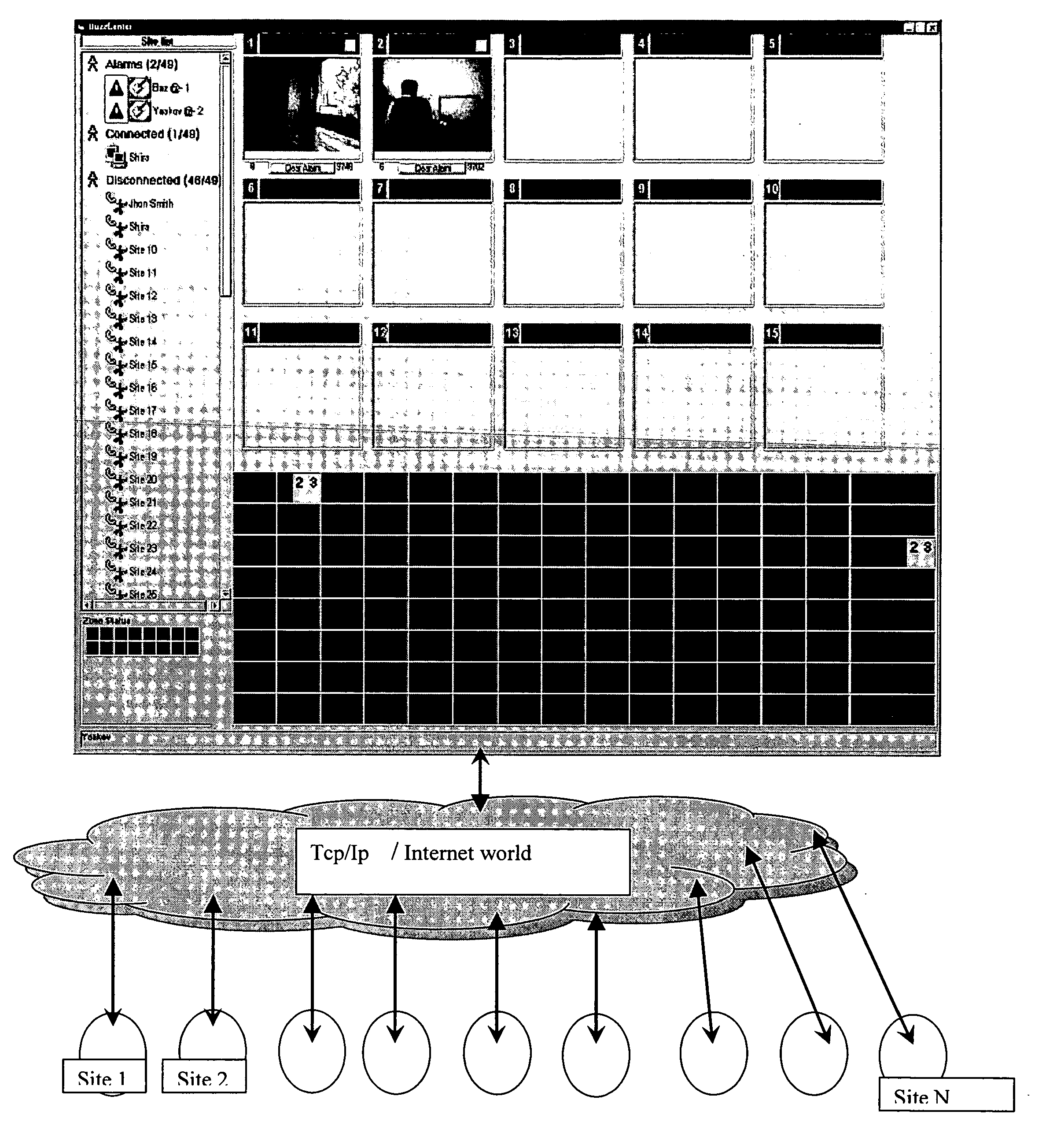
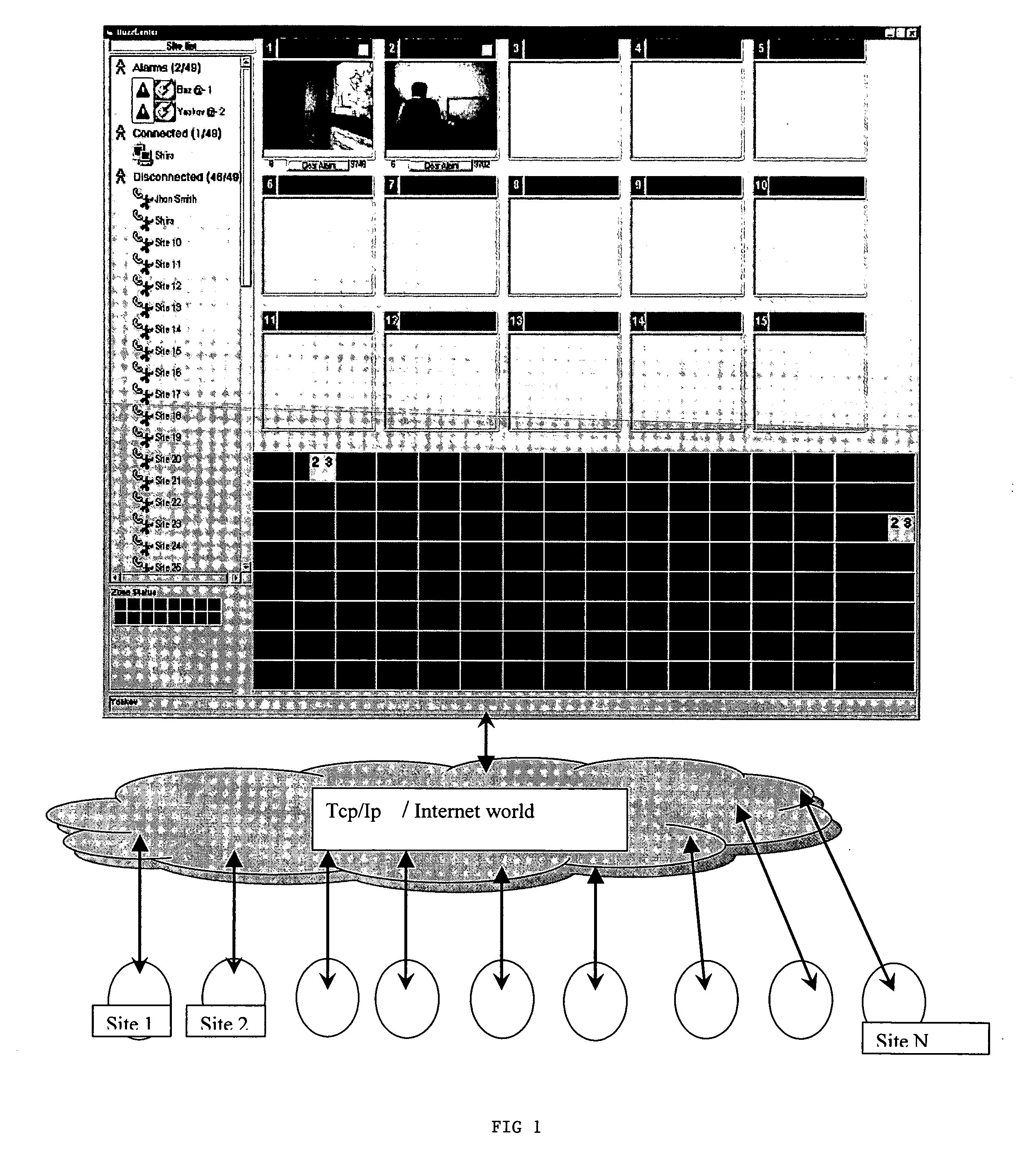
Remote video queuing and display system
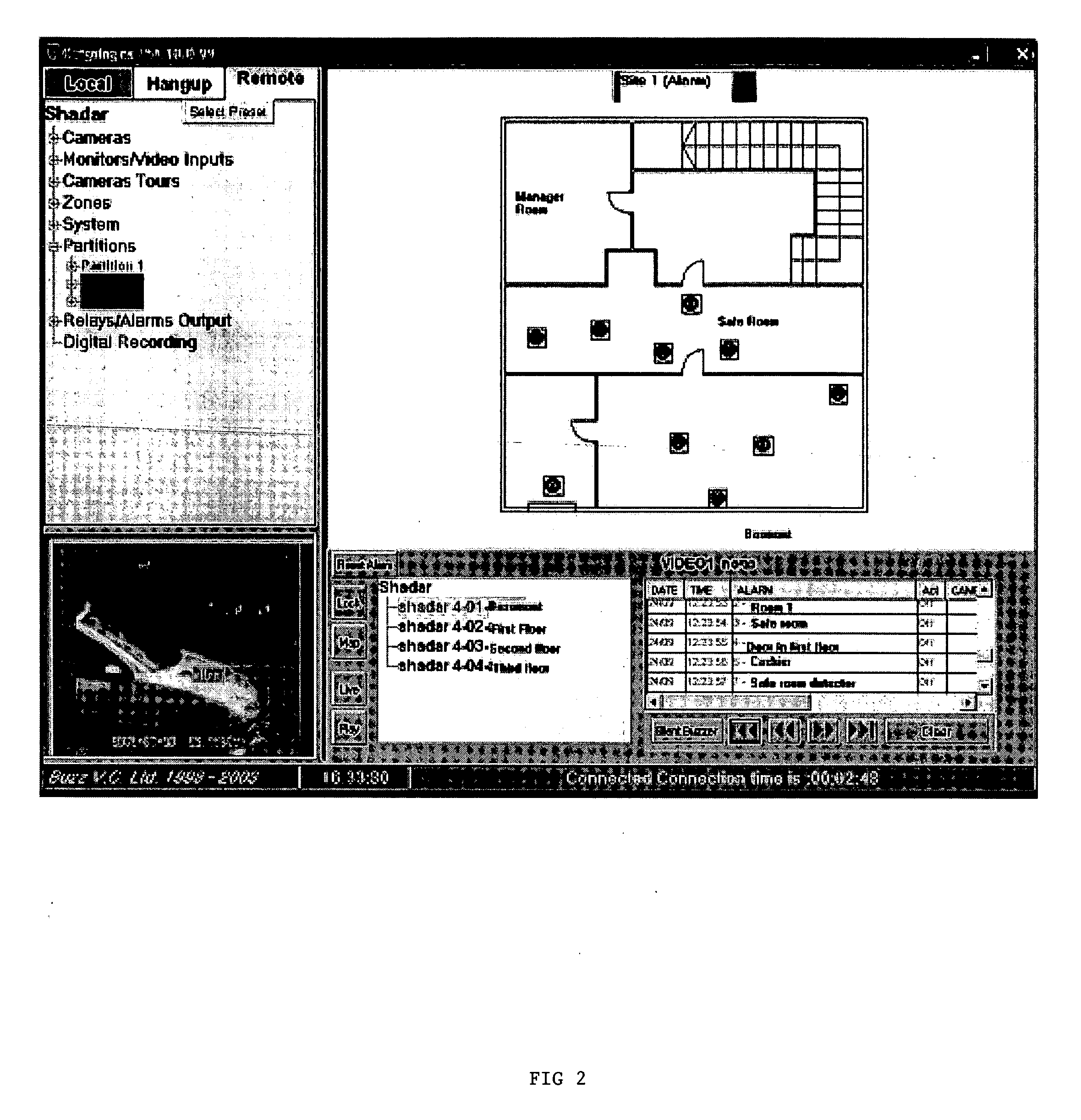
a video monitoring and display system technology, applied in the field of remote video monitoring systems, can solve the problems of not allowing the operator to remotely view video feed from off-site locations over a distributed network, not allowing the operator to control video equipment, video recorders, closed-circuit television surveillance equipment, etc., and needing expensive, proprietary video surveillance and monitoring equipmen
- Summary
- Abstract
- Description
- Claims
- Application Information
AI Technical Summary
Problems solved by technology
Method used
Image

Examples
operation example
[0027] Step 1: Wait and listen on port 9700. [0028] Step 2: CONNECTION_REQUEST received? Accept on another Winsock. (To keep the first one free for other requests) [0029] Step 3: If the site does not have an assigned channel already, assign a new one, otherwise use the already assigned. [0030] Step 4: Send the channel number to the site, notify Master about the new attempt. [0031] Step 5: If the connection is closed (Site got the new channel number, will close the connection and attempt a new connection on the new channel), free this Winsock. [0032] Step 6: CLOSE MSG received? Cleanup any open Winsock, exit the program.
Control Center (Master) Process: [0033] 1—Show the GUI Wait for Messages: [0034] 2—ADD_CHANNEL received? Read the details from the INI file. Add the site to the list if doesn't exist already. Launch a new “Client” process for this site. [0035] 3—Save the handle of the new process so we can send it messages. [0036] 4—Send the client its channel number. [0037] 5—CHANN...
PUM
 Abstract
Description
Claims
Application Information