
Electro-magnetic propagation modeling

a propagation modeling and electromagnetic technology, applied in the field of telecommunications, can solve the problems of high cost, inability to accurately predict the location of the path, and inability to accurately predict the path, so as to achieve the effect of convenient tuning, efficient computer implementation and calculation, and admissibility

Active Publication Date: 2008-10-07
POLARIS WIRELESS
View PDF4 Cites 47 Cited by
  • Summary
  • Abstract
  • Description
  • Claims
  • Application Information

AI Technical Summary

Benefits of technology

[0047]The present invention is predicated on the insight that nearly every type of propagation model can be cast, at least approximately, as a system of linear equations represented by a matrix, and that, consequently, the many advantages of matrix-based models can be extended to a much wider population of propagation models. In particular, matrix-based models have the advantage of efficient computer implementation and calculation, ease of tuning, and admissibility (i.e., the tuned parameters of a linear matrix model are guaranteed to be the global optimum). In addition, the illustrative embodiment of the present invention enables a plurality of propagation models to be aggregated into a single matrix-based model, and enables the tuning of a subset of parameters in such aggregate models.

Problems solved by technology

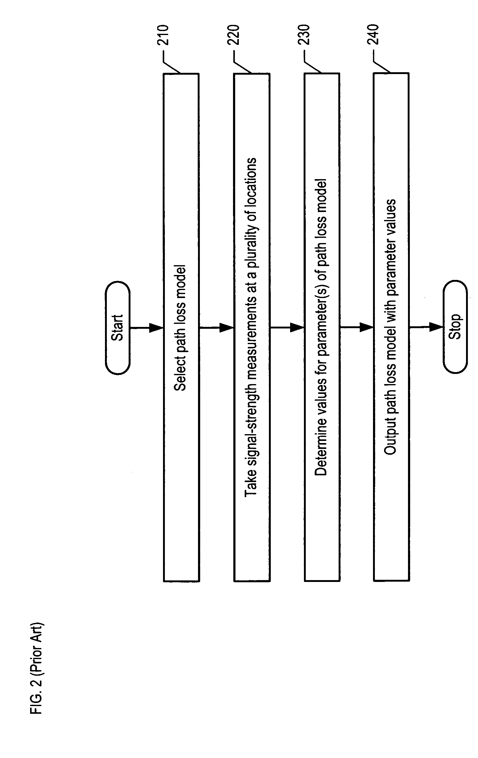
Although this provides an accurate map, it is usually prohibitively expensive because there are often a large number of locations at which measurements need to be taken.
The production and updating of path-loss maps has historically been difficult and expensive, and path-loss maps are often inaccurate at specific locations.
In fact, some industrial path-loss maps are off as much as 15 to 20 dB at specific locations, which effectively eliminates their usefulness in estimating the location of a wireless terminal based on signal-strength measurements.
It is not unusual, however, for these models to produce errors of predicted versus empirical measurements of 10 to 20 dB.
The path loss exponent n that minimizes the standard deviation is useful for gaining quick insight into the general propagation; however, this technique often leads to large, unacceptable standard deviations for prediction at specific locations.
In the 1990s there was a big push in the research community to develop ray tracing techniques for propagation prediction, particularly because the industry was anticipating the proliferation of wireless base stations and prior statistical models, as described above, were ill-suited for the proliferation of wireless base stations.
Practitioners of ray-tracing found, however, that while the technique afforded a little more accuracy than prior approaches, it suffered from huge computational costs.
Moreover, ray tracing is not a very convenient or scalable technology: engineers often had to spend inordinate amounts of time formatting the maps and data required as inputs to a ray-tracing software engine.
This class of propagation models, initially developed for indoor usage, was based on basic information such as building blueprints and typically resulted in standard deviation errors of 5-10 dB.
As is well-known to those skilled in the art, the components of {right arrow over (x)} cannot be solved directly when there are more measured points in {right arrow over (p)} than unknowns in {right arrow over (x)} because it is an over-determined system of equations.

Method used


Image

  • Electro-magnetic propagation modeling
  • Electro-magnetic propagation modeling
  • Electro-magnetic propagation modeling

Examples


Embodiment Construction

[0060]FIG. 3 depicts a flowchart of the salient tasks performed in accordance with the illustrative embodiment of the present invention. It will be clear to those skilled in the art, after reading this disclosure, which tasks depicted in FIG. 3 can be performed concurrently or in a different order than that depicted.

[0061]At task 301, an path-loss model is cast in the matrix model framework as depicted in Equations 14a and 14b.

[0062][p1p2⋮pM]=[a11a12⋯a1⁢Na21a22⋯a2⁢N⋮⋮⋰⋮aM⁢⁢1aM⁢⁢2⋯aMN]⁡[x1x2⋮xN](Eq.⁢14⁢a)p→=A⁢⁢x→(Eq.⁢14⁢b)

[0063]Model matrix A comprises coefficients aij, wherein iε{1, 2, . . . , M} and jε{1, 2, . . . , N}, and wherein coefficients aij have any type of values (e.g., cardinal numbers, non-integer values, etc.) that are based on a particular propagation model and a particular geographic area. Parameter vector {right arrow over (x)} contains tunable parameters of the propagation model, and path-loss vector {right arrow over (p)} contains the path-loss measurements or pred...


PUM


Abstract

A generalized framework is disclosed in which a wide variety of propagation models can be cast in a matrix-based format using arbitrary matrix coefficients. Casting propagation models in the matrix-based framework enables efficient computer implementation and calculation, ease of tuning, admissibility, and aggregating multiple propagation models into a single matrix-based model. Matrix-based propagation models based on transmitter-receiver azimuth orientation, transmitter antenna height, terrain elevation, and clutter are also disclosed. The propagation models can be used in conjunction with automated data acquisition from information sources such as topographic maps, clutter maps, etc.

Description

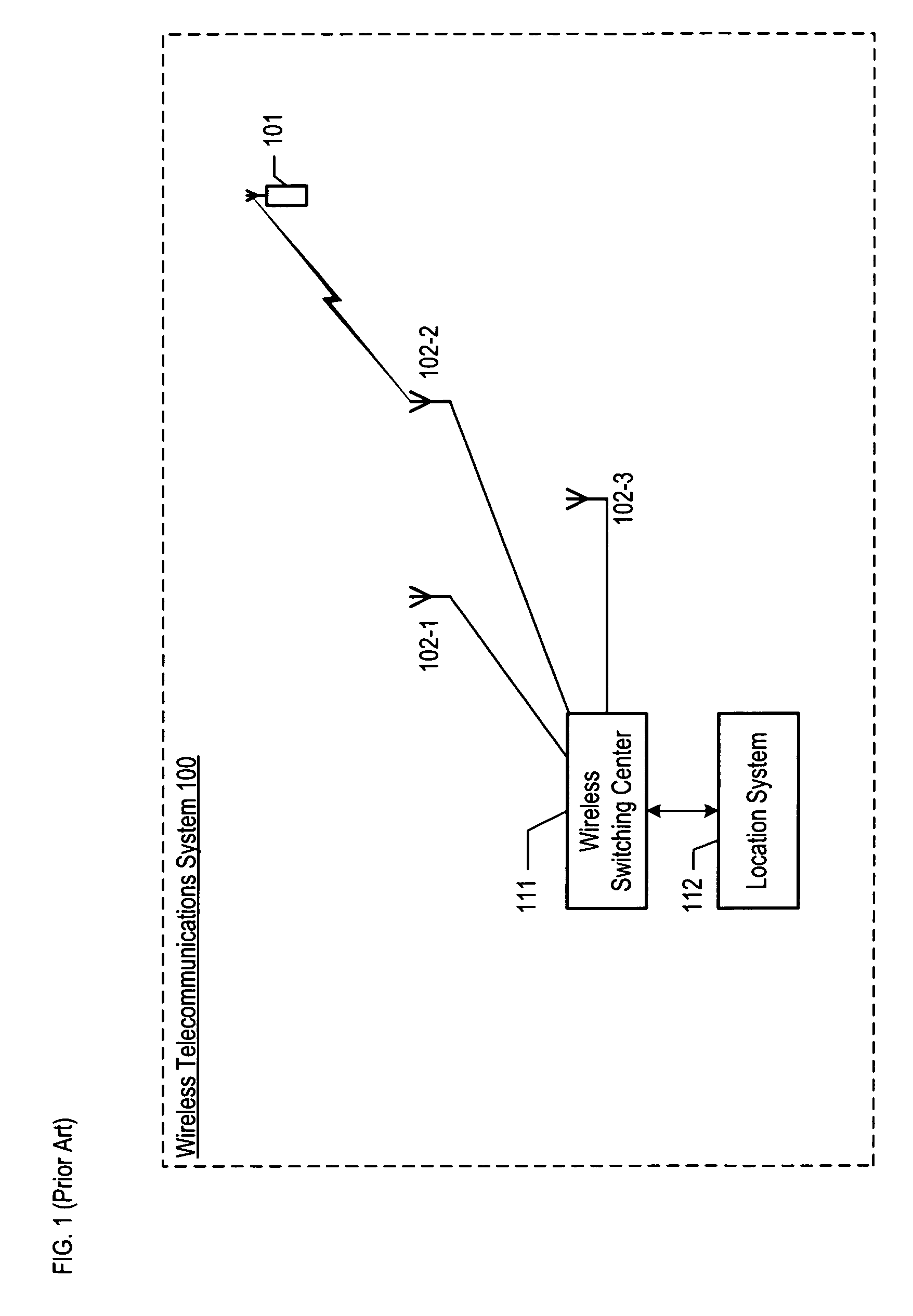
FIELD OF THE INVENTION[0001]The present invention relates to telecommunications in general, and, more particularly, to techniques for modeling the electro-magnetic path-loss in an environment.BACKGROUND OF THE INVENTION[0002]FIG. 1 depicts a schematic diagram of wireless telecommunications system 100 which provides wireless telecommunications service to wireless terminal 101 within a region. The heart of the telecommunications system is wireless switching center 111, which might also be known as a mobile switching center (“MSC”) or a mobile telephone switching office (“MTSO”).[0003]Typically, wireless switching center 111 is connected to a plurality of base stations (e.g., base stations 102-1, 102-2, and 102-3), which are dispersed throughout the geographic area serviced by the system. As depicted in FIG. 1, base station 102-2 serves wireless terminal 101.[0004]As is well known to those skilled in the art, wireless switching center 111 is responsible for, among other things, establi...

Claims


Application Information

Patent Timeline
Patent Type & Authority Patents(United States)
IPC IPC(8): H04B17/00
CPCH04B17/318
Inventor DURGIN, GREGORY D.
Owner POLARIS WIRELESS
Learn More