Lightning protection device and method

a protection device and protection device technology, applied in the field of lightning air terminals, can solve the problems of difficult laboratory experiments to readily model the field decay, and the value will never be exact, and achieve the effect of avoiding the need for exact values

Active Publication Date: 2005-07-07
ERICO INT
View PDF7 Cites 23 Cited by
  • Summary
  • Abstract
  • Description
  • Claims
  • Application Information

AI Technical Summary

Problems solved by technology

Streamer development fields may also be determined in the laboratory, but it has proven difficult to perform laboratory experiments to readily model the field decay from the surface to

Method used


Image

  • Lightning protection device and method
  • Lightning protection device and method
  • Lightning protection device and method

Examples


Embodiment Construction

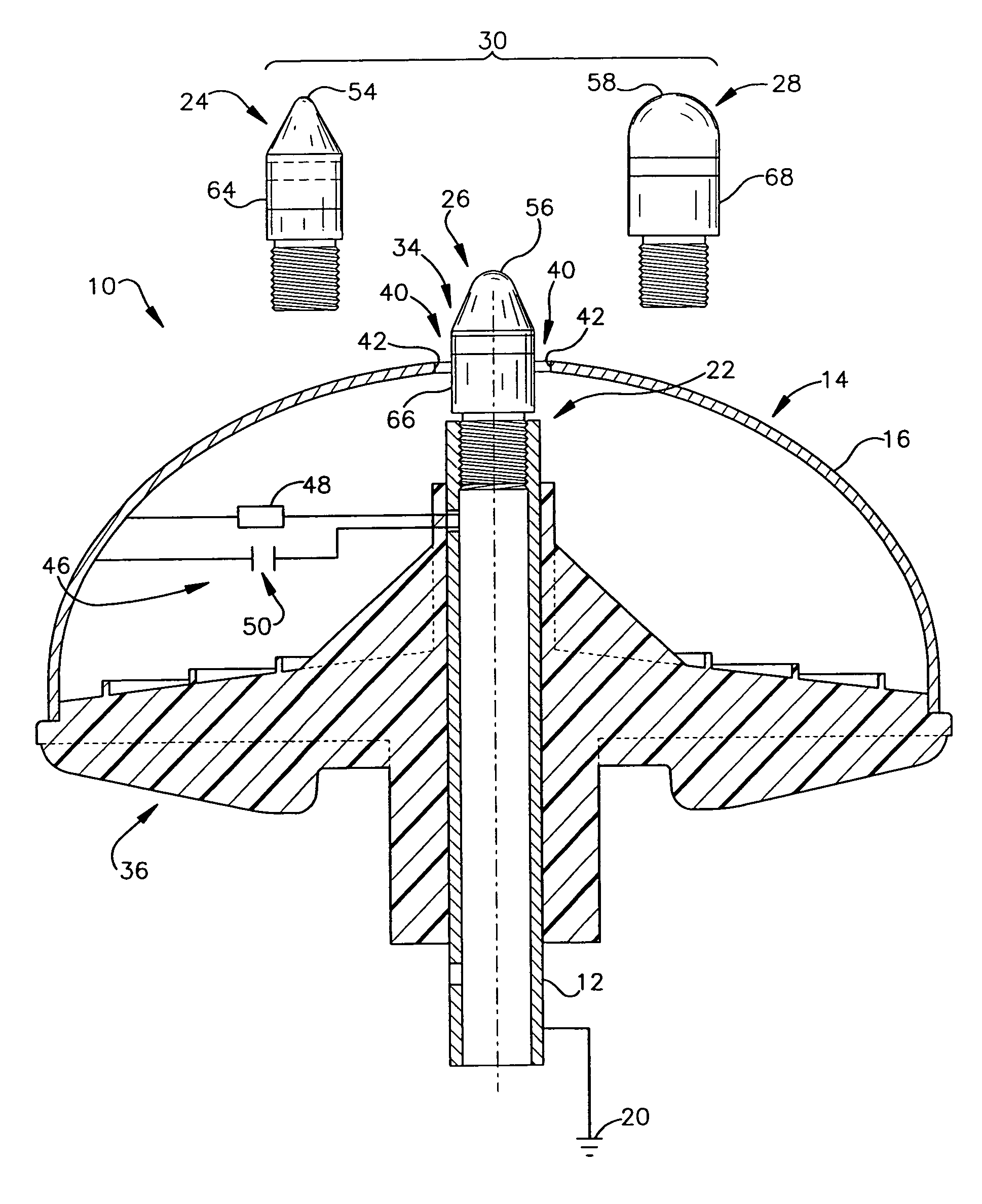
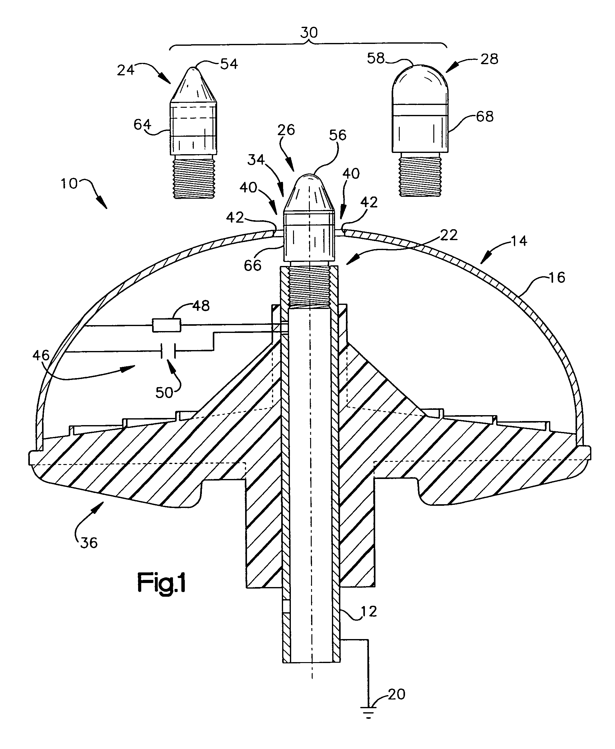
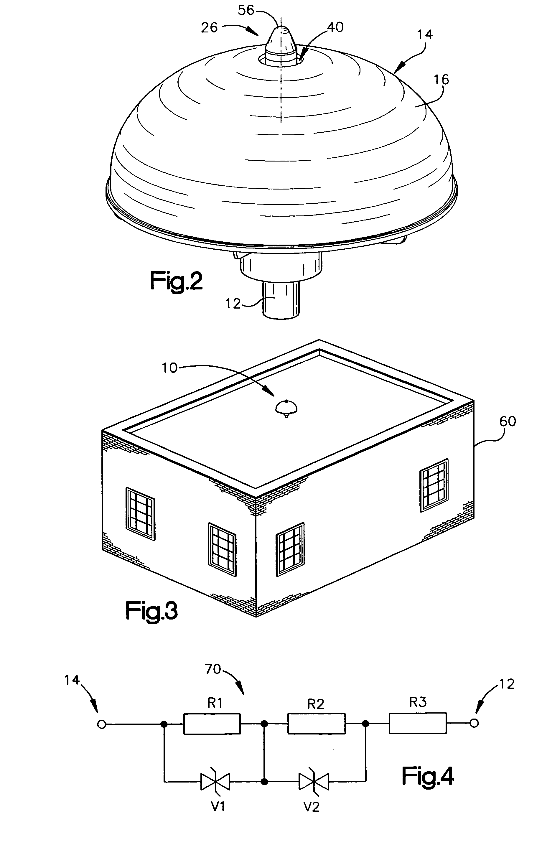
[0039] An air terminal for lightning protection includes a central rod and a curved conductive surface around the central rod. The central rod includes a tip mount for receiving a tip from a tip set that includes a plurality of tips that impart different electrical characteristics to the air terminal. For example, the tips of the tip set may have a variety of radii of curvature, and may provide different gap sizes between the various tips and the curved conductive surface. The curved conductive surface and the grounded central rod may be coupled together via an electrical connection. The electrical connection may include a fixed impedance or resistance, or may include a variable impedance unit that automatically varies impedance based on a voltage difference between the curved conductive surface and the grounded central rod. The tip set with plurality of tips, and / or the variable impedance unit, may allow for improved performance of the air terminal for a variety of installation sit...


PUM


Abstract

An air terminal for lightning protection includes a central rod and a curved conductive surface around the central rod. The central rod includes a tip mount for receiving a tip from a tip set that includes a plurality of tips that impart different electrical characteristics to the air terminal. For example, the tips of the tip set may have a variety of radii of curvature, and may provide different gap sizes between the various tips and the curved conductive surface. The curved conductive surface and the grounded central rod may be electrically coupled together via an electrical connection. The electrical connection may include a fixed impedance or resistance, or may include a variable impedance unit that automatically varies impedance based on a voltage difference between the curved conductive surface and the grounded central rod.

Description

BACKGROUND OF THE INVENTION [0001] 1. Field of the Invention [0002] This invention relates generally to lightning protection devices and methods, and more particularly to lightning air terminals and a method of design and application of such terminals. [0003] 2. Description of the Related Art [0004] In the field of practical lightning protection, there is a wide spectrum of technologies currently being used. At one end of this spectrum there are the air terminals claiming enhanced or more consistent performance. Whether these terminals enhance or retard corona development, or whether they are blunt or sharp, they have been broadly categorized under a generic term “ESE” meaning Early Streamer Emission. [0005] In the center of the spectrum there is the conventional practice widely specified in various Standards. This practice currently uses an “electrogeometric” model known as the “rolling sphere method” which was adapted from lightning strike measurements relevant to the electric pow...

Claims


Application Information

Patent Timeline
IPC IPC(8): H02G13/00
CPCH02G13/00H02G13/40H02G13/80
Inventor D'ALESSANDRO, FRANCO
Owner ERICO INT
Why Eureka
Try Eureka