Image matching apparatus, image matching method, and image matching program

Inactive Publication Date: 2005-07-07
FUJITSU LTD
View PDF4 Cites 65 Cited by
  • Summary
  • Abstract
  • Description
  • Claims
  • Application Information

AI Technical Summary

Benefits of technology

[0064] According to the eighteenth aspect of the present invention, in the image mat

Problems solved by technology

Additionally, when a finger is too strongly pressed, or a finger is moved while pressed to a sensor, the image input from the sensor can be fat or distorted.
When an image is registered as an image to be matched with a broken or distorted portion included in the image, there occurs the problem of low accuracy for an arithmetic result of an evaluation value.
However, with an increasing number of small computers of late, small sensors are also required for image

Method used


Image

  • Image matching apparatus, image matching method, and image matching program
  • Image matching apparatus, image matching method, and image matching program
  • Image matching apparatus, image matching method, and image matching program

Examples


first embodiment

[0104] The first embodiment of the present invention is the basic component of the image matching apparatus, the image matching method, and the image matching program.

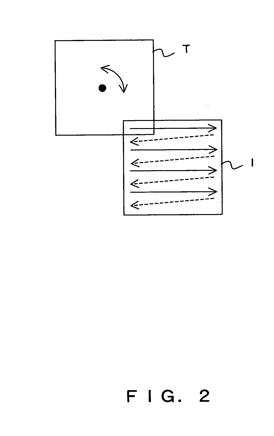
[0105] As shown in FIG. 6A, an image T is matched with an image I.

[0106] First, as shown in FIG. 6B, to adjust the relative position relationship or the relative rotation angle relationship between the image T and the image I, a partial image S is segmented from the image T. The method for determining the position of the partial image S is described later.

[0107] As shown in FIG. 6C, correlation arithmetic is performed using a partial image S and an image I. That is, a correlation value (a value indicating the overlap between two images) is calculated while displacing the relative position between the partial image S and the image I by n pixels (n indicates an integer of 1 or larger). Furthermore, the rough adjustment is similarly performed while rotating the partial image S little by little. The correlation value ca...

second embodiment

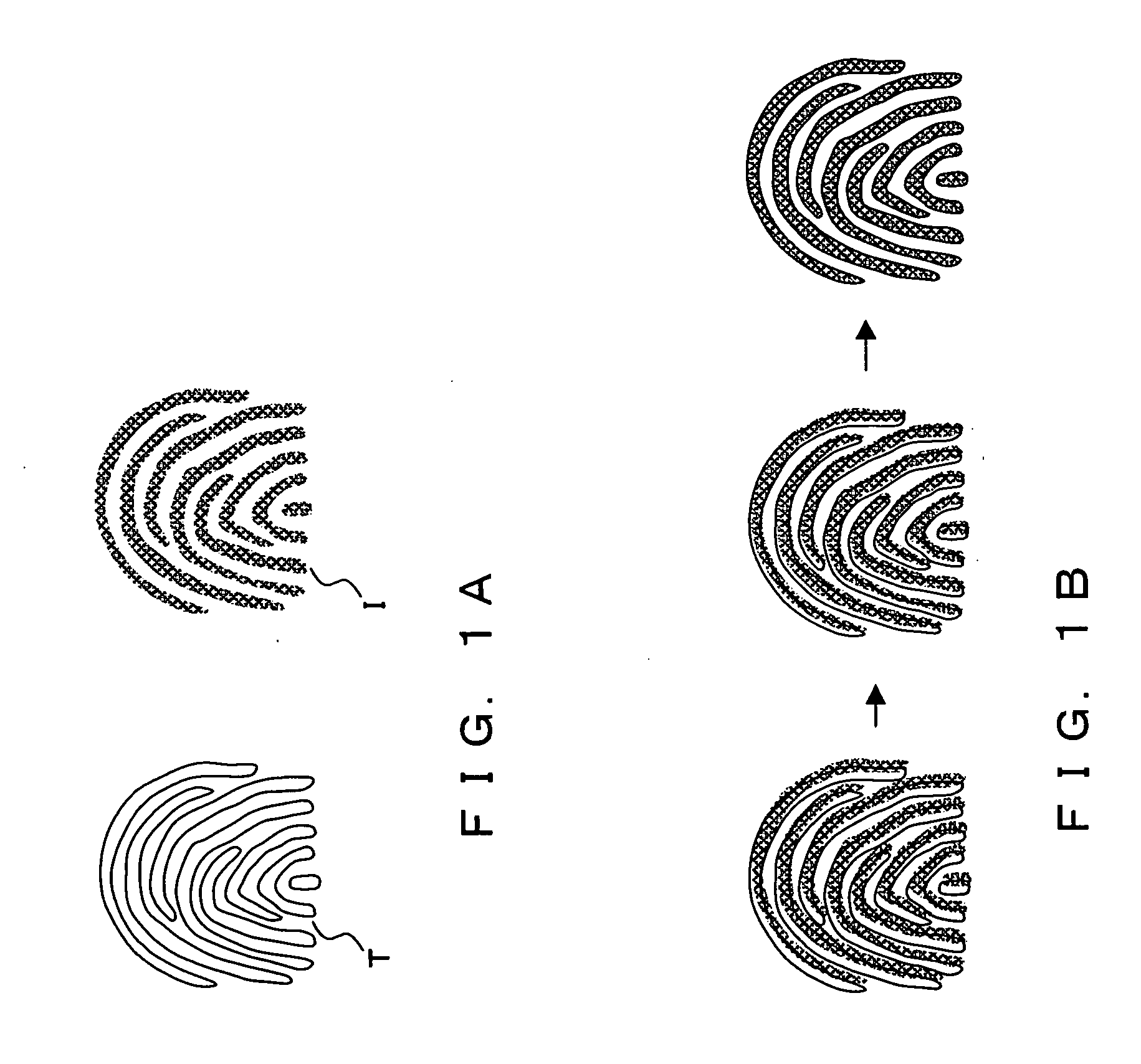
[0146] In the second embodiment of the present invention, the practical method for extracting a partial image S in matching fingerprint images is described. When fingerprint images are matched, the position of the partial image S to be segmented from the image T can be set as follows to obtain the relative position and relative angle between the image T and the image I with high accuracy.

[0147] 1. Center (indicating a large curvature of the ridgeline on the entire fingerprint image) and delta

[0148] 2. Feature point (endpoint, branch point).

[0149] First, assume the case in which “1. center and delta” is included in the partial image S.

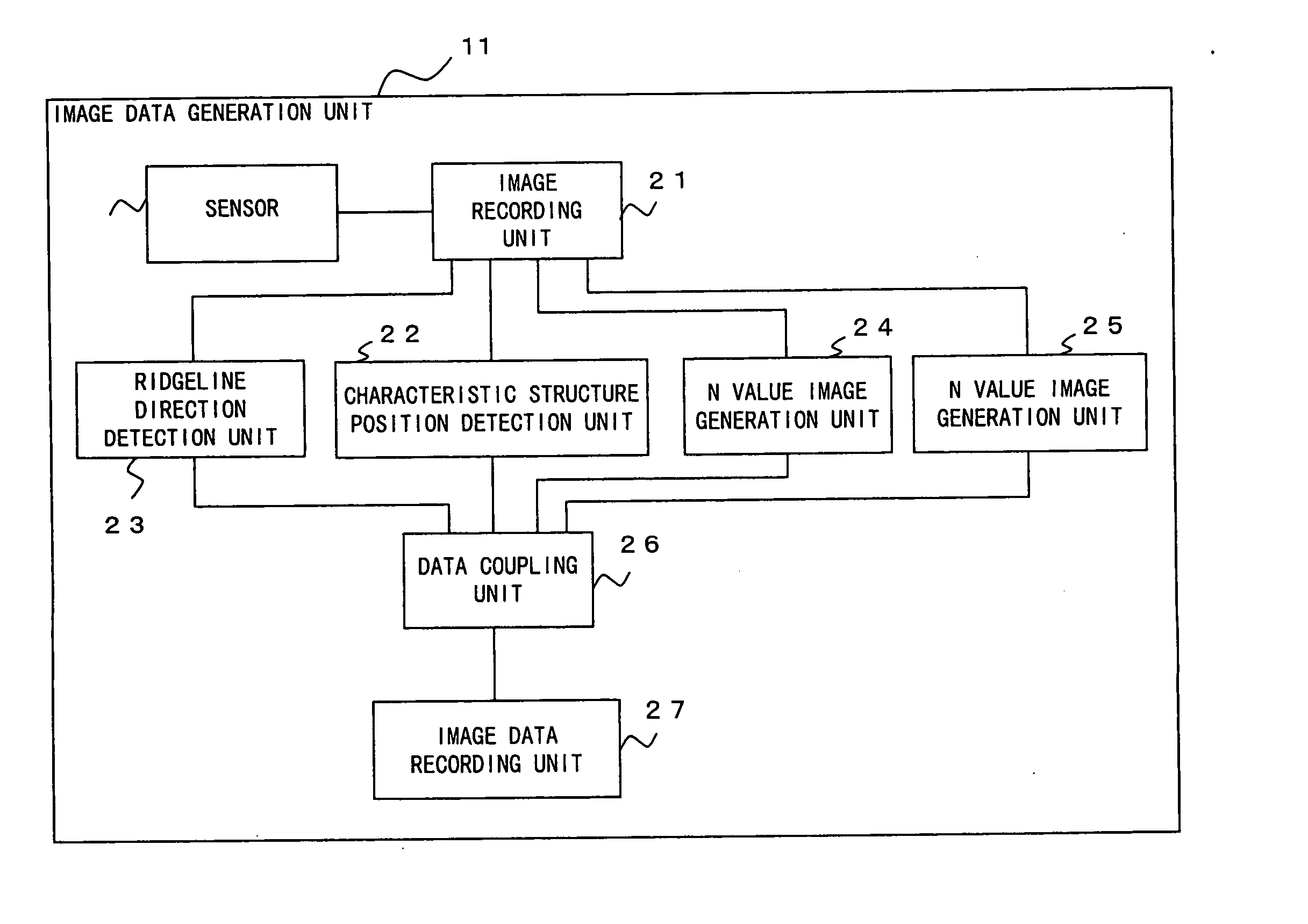
[0150]FIG. 11 is a flowchart for explanation of the operation of the image data generation unit 11 when “1. center and delta” is included in the partial image S.

[0151] First, in step C1, the ridgeline direction detection unit 23 extracts a predetermined image T from the image recording unit 21, and obtains the ridgeline direction distribution view ...

third embodiment

[0167] In the first embodiment, the relative position and relative angle of the image T and the image I are obtained using the partial image S, and using the obtained relative position and relative angle, the image T and the image I are superposed, thereby determining whether or not the image T matches the image I.

[0168] According to the third embodiment, to perform matching between two images with higher accuracy, the relative position and the relative angle between the image T and the image I are obtained using the entire image other than the partial image S, and it is determined whether or not the image T matches the image I. That is, when image matching is performed, a rough adjustment is made on the relative position and the relative angle between the image T and the image I using the partial image S, and then a fine adjustment is made based on the relative position and the relative angle obtained by the rough adjustment between the image T and the image I using the entire ima...


PUM


Abstract

When two images are matched, a partial image S is registered in advance, mutual relative position is obtained when the partial image S and an image I indicate the largest overlap. Based on the relative position, the relative position between the image T and the image I is determined. Thus, it is determined whether or not the image T and the image I match.

Description

CROSS REFERENCE TO RELATED APPLICATION [0001] This application is a continuation of international PCT application No. PCT / JP03 / 04784 filed on Apr. 15, 2003.BACKGROUND OF THE INVENTION [0002] 1. Field of the Invention [0003] The present invention relates to image matching using a pattern matching method, and more specifically to an image matching apparatus, an image matching method, and an image matching program for matching fingerprint images, etc. [0004] 2. Description of the Related Art [0005] When a specific object (an image of a person, a face, a combat car, etc.) is extracted from an image, and a matching operation is performed to check whether or not predetermined images (fingerprint images, face images, iris images, etc.) match, a image matching method that is called a pattern matching method is widely used. In the pattern matching method, the shapes of the characteristic portions and the similar portions in density distribution between a registered image (hereinafter referre...

Claims


Application Information

Patent Timeline
IPC IPC(8): G06K9/00G06K9/32G06T7/00
CPCG06K9/00087G06K9/3216G06K9/001G06V40/1365G06V40/1376G06V10/245
Inventor FUJII, YUSAKU
Owner FUJITSU LTD
Why Eureka
Try Eureka