Eureka AIR delivers breakthrough ideas for toughest innovation challenges, trusted by R&D personnel around the world.

Image compression encoding apparatus and image compression encoding method, and program

a technology of image compression and encoding apparatus, applied in the field of image compression encoding apparatus and image compression encoding method, can solve the problems of reducing information quantity and the inability to completely maintain original image quality, and achieve the effect of efficient selection of dct encoding system

Inactive Publication Date: 2005-07-07
SONY CORP
View PDF4 Cites 19 Cited by
  • Summary
  • Abstract
  • Description
  • Claims
  • Application Information

AI Technical Summary

Benefits of technology

The present invention provides an image compression encoding apparatus and method that can efficiently select the best compression system for each block of an image while satisfying target code quantity. Code quantity from different paths can be selected efficiently, and code quantity from the DPCM path is preferentially selected to prevent image quality degradation. The apparatus includes a calculating means for adding code quantities from different compression systems to calculate total code quantity, a selecting means for selecting the best compression system based on the total code quantity and target code quantity, and a compression-encoding means for compressing the image signal using the selected compression system. The invention also provides a computer program for executing the image compression encoding process.

Problems solved by technology

However, image signals are compression-encoded by making use of line correlation or interframe correlation of video signals to thereby have ability to decrease information quantity.
However, in the above-described code quantity control method based on the DCT encoding system, when DCT coefficients are quantized by quantization step selected, e.g., on block basis, any distortion may be added in the process of compression and expansion of image, it is impossible to completely maintain original image quality.

Method used


Image

  • Image compression encoding apparatus and image compression encoding method, and program
  • Image compression encoding apparatus and image compression encoding method, and program
  • Image compression encoding apparatus and image compression encoding method, and program

Examples


Embodiment Construction

[0027] Embodiments of the present invention will now be explained.

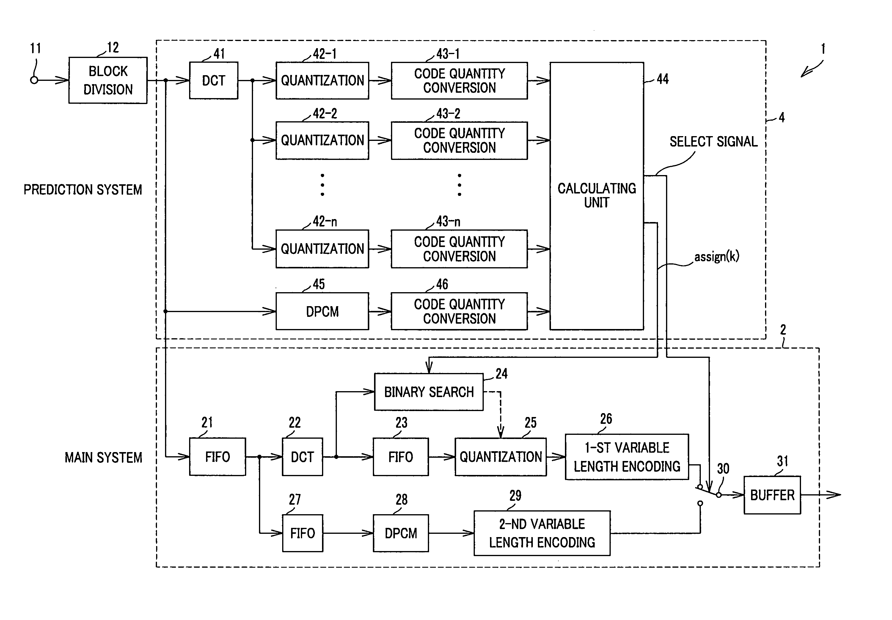
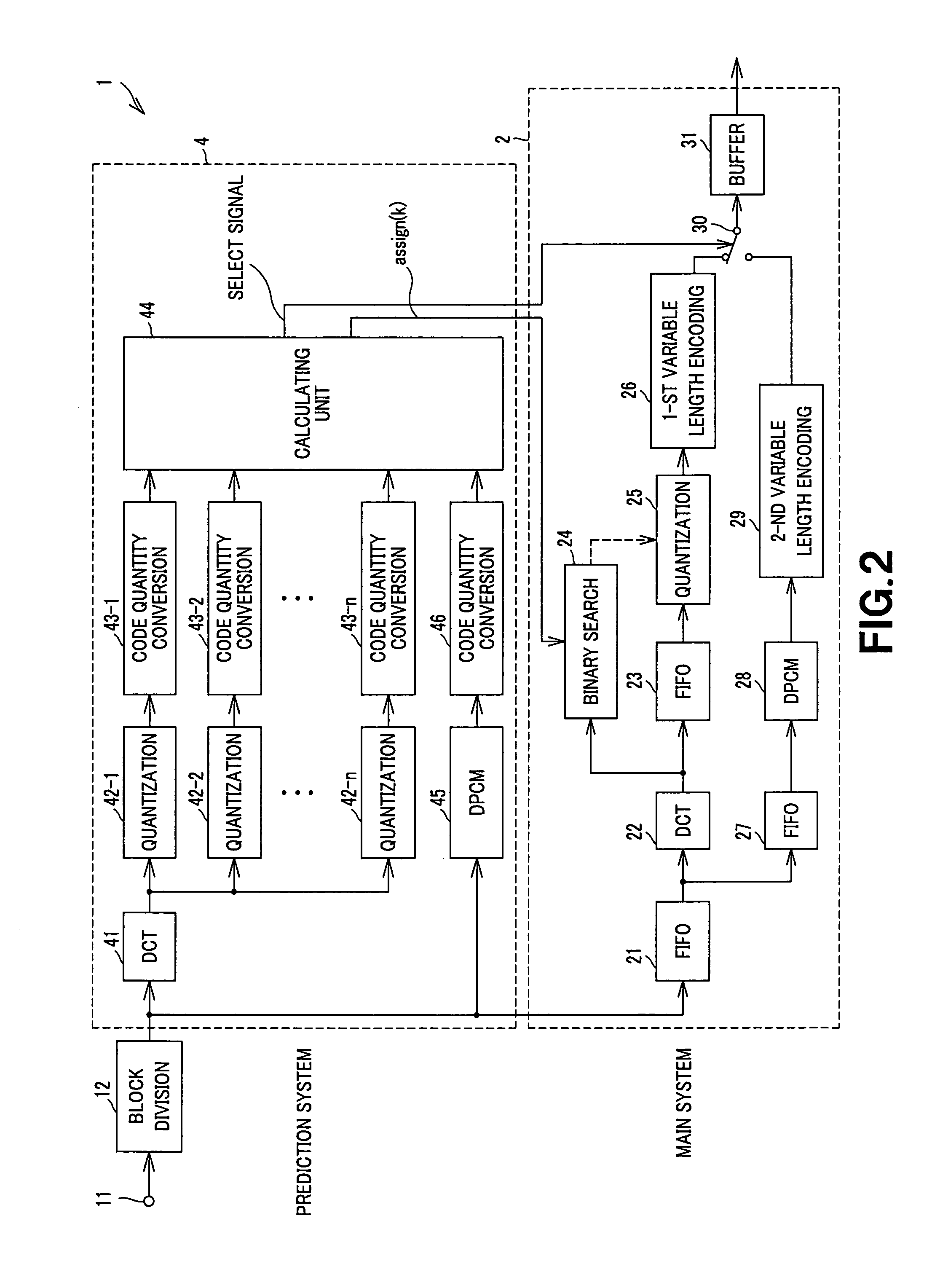
[0028] The image compression encoding apparatus according to this embodiment is adapted to perform, e.g., DCT (Discrete Cosine Transform) of an inputted image signal thereafter to quantize the image signals thus transformed to thereby realize irreversible image compression, or is adapted to realize reversible encoding on the basis of, e.g., DPCM (Differential Pulse Code Modulation), etc.

[0029] As shown in FIG. 2, the image compression encoding apparatus 1 is supplied with an image signal consisting of luminance signal Y and color difference signals Pb, Pr through a terminal 11. The block dividing unit 12 selects an inputted image signal of one frame on encoding system selection basis to transmit the image signal thus selected to a main system 2 and a prediction system 4. This encoding system selection unit (basis) indicates, e.g., block unit of 8×8, macro block unit of 16×16, slice unit, or division into image area ...


PUM


Abstract

In order to preferentially select code quantity from DPCM path in a manner to satisfy the target code quantity to thereby prevent deterioration of image quality, either code quantities obtained by a first compression system of quantizing an input image signal by quantization steps different from each other, or code quantities obtained by a second compression system which has compression factor and loss which are lower than those of the first compression system are added on encoding system selection basis to thereby calculate total code quantity of equi-length unit to compare the calculated total code quantity and target code quantity in the equi-length unit to determine quantization step in the first compression system in accordance with the comparison result to select, on the encoding system selection basis, the first compression system or the second compression system of performing quantization by the determined quantization step.

Description

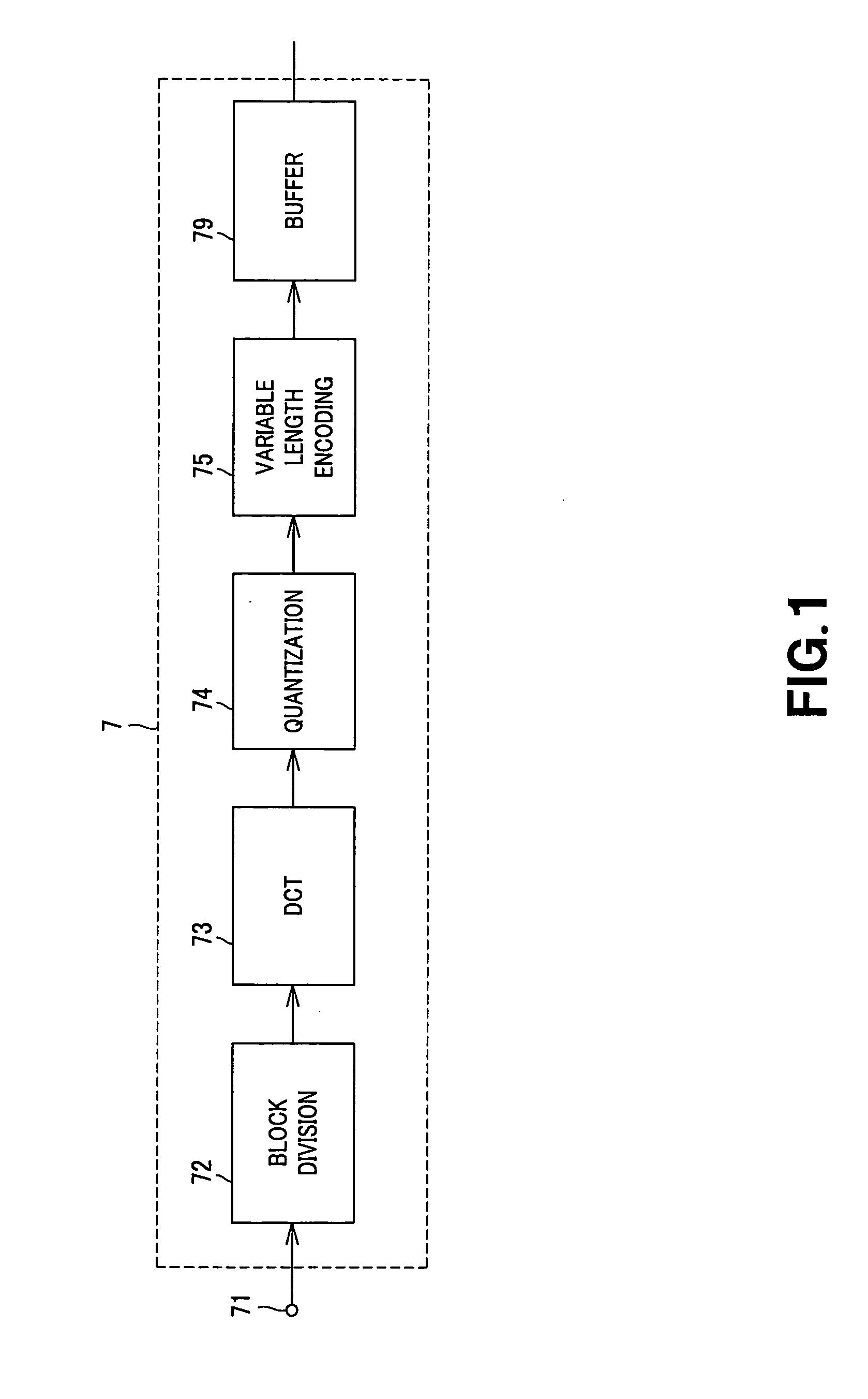
TECHNICAL FIELD [0001] The present invention relates to an image compression encoding apparatus and an image compression encoding method which are applied to, e.g., MPEG (Moving Picture image coding Experts Group), etc., and have ability to control generated information quantity by encoding operation using, e.g., DCT (Discrete Cosine Transform), or DPCM (Differential Pulse Code Modulation). [0002] This Application claims priority of Japanese Patent Application No. 2002-092884, filed on Mar. 28, 2002, the entirety of which is incorporated by reference herein. BACKGROUND ART [0003] For example, in systems for performing transmission of moving picture (image) signals to remote place like television conference system and / or television telephone system, when moving picture signals are digitized as they are, information quantity extremely large. However, image signals are compression-encoded by making use of line correlation or interframe correlation of video signals to thereby have abili...

Claims


Application Information

Patent Timeline
Patent Type & Authority Applications(United States)
IPC IPC(8): G06T9/00H04N7/26H04N7/50
CPCH04N19/176H04N19/147H04N19/15H04N19/115H04N19/61H04N19/90H04N19/126H04N19/152H04N19/154H04N19/192H04N19/42H04N19/12
Inventor KITAMURA, TAKUYA
Owner SONY CORP
Why Eureka
Eureka Blog
Learn More