
System and method for removing ringing artifacts

Inactive Publication Date: 2005-07-07
SHARP KK
View PDF15 Cites 160 Cited by
  • Summary
  • Abstract
  • Description
  • Claims
  • Application Information

AI Technical Summary

Benefits of technology

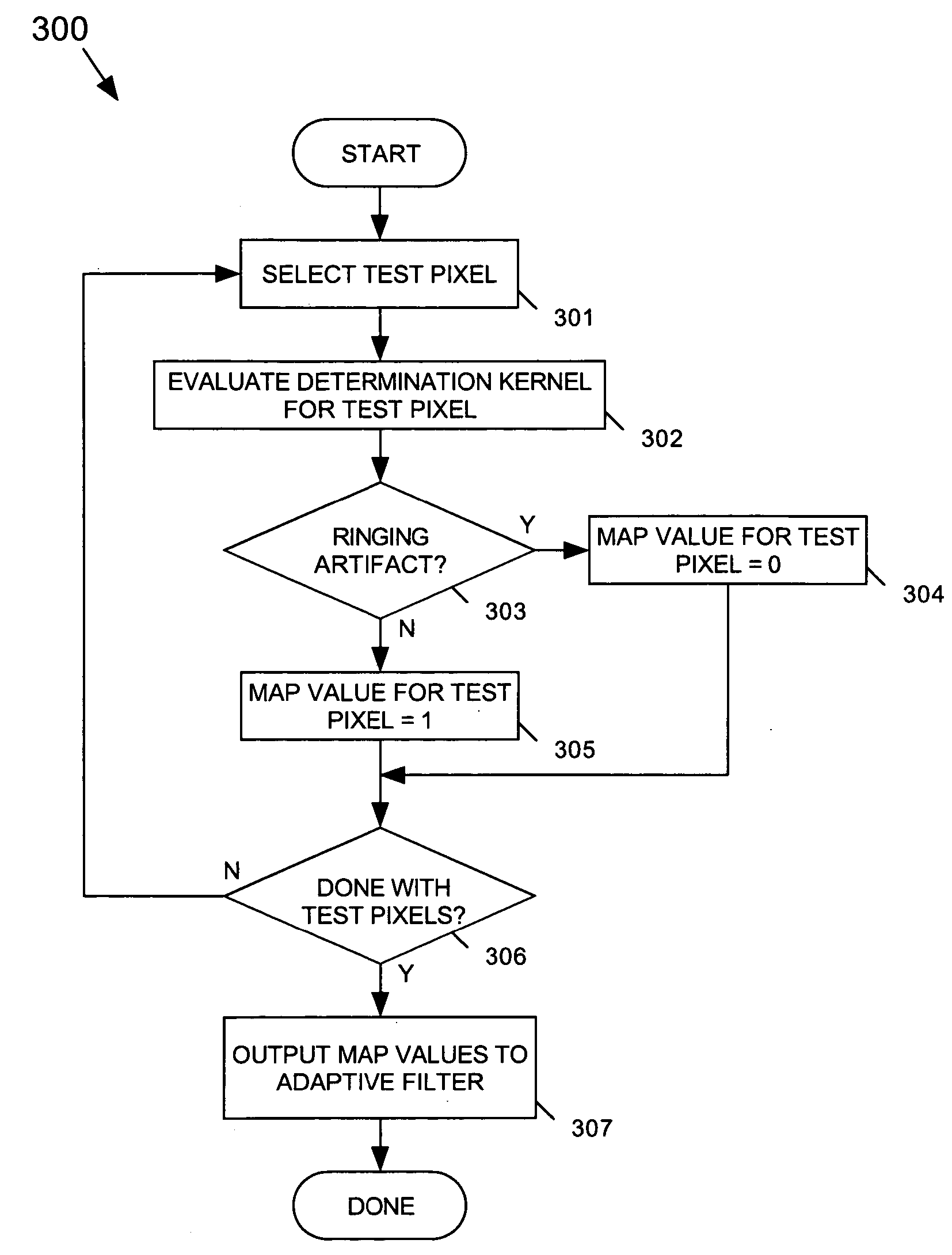
[0018] Another exemplary embodiment of the present invention provides a method for removing ringing artifacts from an image in which a low-pass-filter window E is selected for each respective selected pixel of a first set of selected pixels of an image. A low-pass-filtered gray-level value is then generated for each respective selected pixel based on at least one selected characteristic of the pixels contained in the low-pass-filter window E corresponding to the selected pixel. According to the present invention, a selected characteristic of the selected pixel is used to generate the average value when a difference between the selected characteristic of a pixel within the low-pass-filter window E and the corresponding characteristic of the selected pixel is greater than or equal to a predetermined threshold. Additionally, it is determined whether each selected pixel of a second set of selected pixels of an image contains a ringing artifact based on, for example, at least one selected characteristic of selected pixels within a determination kernel of pixels relating to the selected pixel of the second set of selected pixels. A filtered value is generated for each pixel determined to contain a ringing artifact based on, for example, at least one selected characteristic of selected pixels within a filtering kernel of pixels relating to the pixel.

Problems solved by technology

Low bit-rate encoding, however, may cause several types of artifacts in decompressed images, the most notable of which include blocking and ringing artifacts.
Ringing artifacts are typically observed around the true edges of an image and are commonly referred to as mosquito artifacts because they tend to be annoying, especially in moving images (i.e., video sequences).
One drawback of conventional de-ringing filters is that all are computationally intensive.
Consequently, conventional de-ringing filters are not suitable for all receiving systems.
Further, de-ringing filters may cause unacceptable delays, even when implemented.

Method used


Image

  • System and method for removing ringing artifacts
  • System and method for removing ringing artifacts
  • System and method for removing ringing artifacts

Examples


Embodiment Construction

[0033] The present invention provides a low-complexity de-ringing filter that removes ringing artifacts from image information caused by compression. The degree of filtering of de-ringing artifacts is selectively adjustable. The low-complexity de-ringing filter of the present invention can also selectively remove severe coding artifacts when very strong filtering is needed.

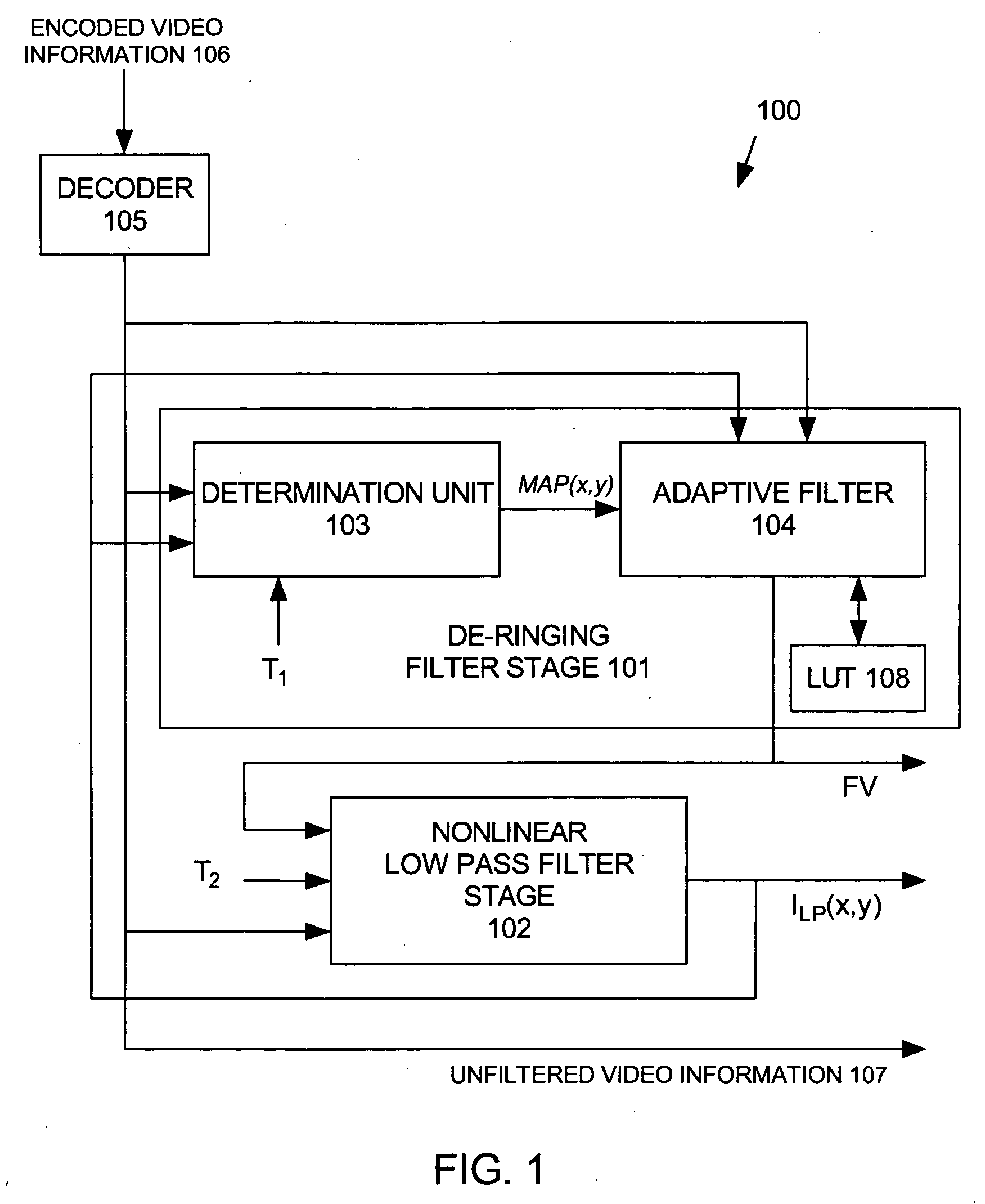
[0034]FIG. 1 shows an exemplary functional block diagram of an image de-ringing system 100 according to the present invention that removes ringing artifacts from image information. Image de-ringing system 100 includes a de-ringing filter stage 101 and a nonlinear low-pass filter (NLPF) stage 102. De-ringing filter stage 101 includes a determination unit 103 and an adaptive filter 104. NLPF stage 102 provides filtering that can be used in conjunction with de-ringing filter stage 101, or can be used alone to enhance the quality of the image information.

[0035] A decoder 105 receives encoded video information 106 th...


PUM


Abstract

Ringing artifacts are removed from a quantized image by an image de-ringing filter that includes a determination unit, an adaptive filter and a nonlinear low-pass filter. The determination unit determines whether each selected pixel of a first set of selected pixels of an image contains a ringing artifact based on, for example, gray-level values of selected pixels within a determination kernel of pixels relating to the selected pixel. The adaptive filter generates a filtered gray-level value for each pixel determined by the determination unit to contain a ringing artifact based on, for example, gray-level values of selected pixels within a filtering kernel of pixels relating to the pixel. The nonlinear low-pass filter generates a low-pass-filtered gray-level value for each selected pixel of a second set of selected pixels of the image.

Description

CROSS-REFERRENCE TO RELATED APPLICATIONS [0001] The present application claims priority to a provisional patent application entitled, METHODS FOR REMOVING RINGING ARTIFACTS, invented by S. Deshpande et al., Ser. No. 60 / 535,045, filed Jan. 6, 2004, which is incorporated by reference herein.BACKGROUND OF THE INVENTION [0002] 1. Field of the Invention [0003] The present invention relates to compressed image and video coding. In particular, the present invention relates to a system and a method for filtering ringing artifacts that may occur as a result of compressed image and video encoding / decoding processes. [0004] 2. Description of the Related Art [0005] Encoding images and video information at a low bit rate saves computation resources and bandwidth. Low bit-rate encoding, however, may cause several types of artifacts in decompressed images, the most notable of which include blocking and ringing artifacts. Ringing artifacts are typically observed around the true edges of an image an...

Claims


Application Information

Patent Timeline
IPC IPC(8): G06K9/40H04N7/26H04N7/30
CPCH04N19/60H04N19/86H04N19/136H04N19/117
Inventor DESHPANDE, SACHIN G.PAN, HAO
Owner SHARP KK
Learn More