Characterization and control of optical dispersion compensating element

a technology of optical dispersion compensation and optical communication system, applied in the field of chromatic dispersion compensation in optical communication system, can solve the problems of limited usable bandwidth of fiber, non-zero dispersion values at all other wavelengths, and dispersion shifted fiber offering only limited relief in a multi-wavelength environmen

Active Publication Date: 2005-07-07
CIENA
View PDF19 Cites 73 Cited by
  • Summary
  • Abstract
  • Description
  • Claims
  • Application Information

AI Technical Summary

Problems solved by technology

In a long optical fiber communications link, chromatic dispersion of the fiber media causes portions of an intensity modulated signal to arrive at the receiver at slightly different times. This temporal pulse distortion leads to intersymbol interference and effectively limits the usable bandwidth of the fiber.
However, dispersion shifted fiber still has a delay slope, which results in nonzero dispersion values at all other wavelengths.
Thus, dispersion shifted fiber offers only limited relief in a multi-wavelength environment.
Because of the manner in which it is fabricated, a typical dispersion compensating grating exhibits a delay versus wavelength response that is not perfectly smooth.
In situations where the average compensation of the dispersion compensating grating may appear adequate for use in a given optical path, the localized delay ripple characteristics of the dispersion compensating grating may render it unsuitable for use at some wavelengths and modulation rates.

Method used


Image

  • Characterization and control of optical dispersion compensating element
  • Characterization and control of optical dispersion compensating element
  • Characterization and control of optical dispersion compensating element

Examples


Embodiment Construction

[0026] The making and using of various illustrative embodiments are discussed in detail below. It should be appreciated, however, that the present invention provides many applicable inventive concepts that can be embodied in a wide variety of specific contexts. The specific embodiments discussed are merely illustrative of specific ways to make and use the invention, and do not limit the scope of the invention. It will be apparent that many of the present teachings may be applicable to the characterization of dispersion compensating modules and tunable dispersion compensating modules, regardless of whether or not a fiber Bragg grating is employed as the dispersion-affecting element.

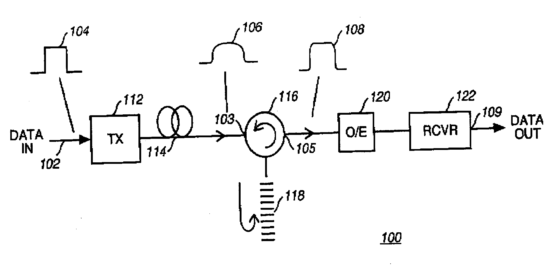
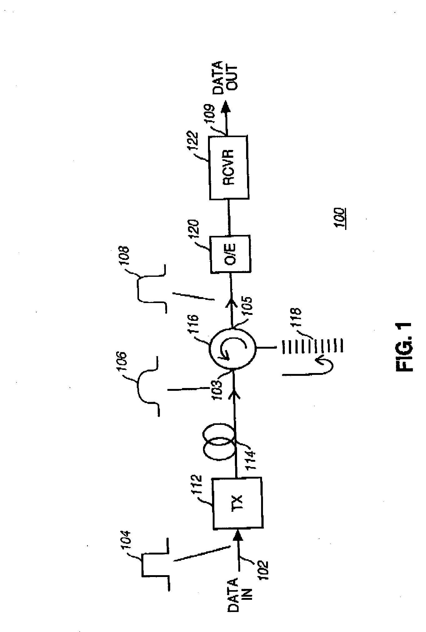
[0027]FIG. 1 illustrates a typical optical communications link 100 employing a fiber Bragg grating to compensate for dispersion caused by propagation through a long optical fiber. Optical transmitter 112 emits an optical carrier signal of a particular wavelength. This carrier signal is intensity modulated...


PUM


Abstract

An apparatus and method are applied to characterizing an dispersion-affecting element for use in controlling chromatic dispersion in an optical communications link. Information regarding the behavior of the dispersion-affecting element is recorded and stored in a medium that is provided for deployment with the dispersion-affecting element to enable improved management and active control of the dispersion-affecting element. The suitability of the dispersion-affecting element for operating under different conditions may also be characterized.

Description

FIELD OF THE INVENTION [0001] The present invention relates generally to chromatic dispersion compensation in optical communications systems, and more particularly to a method and system for predicting or improving the performance of a dispersion compensating element in an optical communications system. BACKGROUND [0002] In a long optical fiber communications link, chromatic dispersion of the fiber media causes portions of an intensity modulated signal to arrive at the receiver at slightly different times. This temporal pulse distortion leads to intersymbol interference and effectively limits the usable bandwidth of the fiber. The dispersion experienced through a given fiber is proportional to both the wavelength carried and the length of the fiber. [0003] A typical single mode fiber will exhibit a dispersion of about 17 picoseconds per nanometer per kilometer (ps / nm-km) at a wavelength of 1545 nanometers. The dispersion changes with a positive slope of about 0.09 ps / nm-km per nm as...

Claims


Application Information

Patent Timeline
Patent Type & Authority Applications(United States)
IPC IPC(8): H04B10/00H04B10/18
CPCH04B10/2519
Inventor FEE, JOHN A.MCKIEL, FRANK A. JR.
Owner CIENA
Why Eureka
Try Eureka