Surgical robotic tools, data architecture, and use

a robotic tool and robotic technology, applied in the field of robotic surgery, can solve the problems of many new challenges, many independent surgical manipulators, and surgeons will typically employ a significant number of different surgical instruments

Inactive Publication Date: 2005-07-07
INTUITIVE SURGICAL OPERATIONS INC
View PDF100 Cites 106 Cited by
  • Summary
  • Abstract
  • Description
  • Claims
  • Application Information

AI Technical Summary

Benefits of technology

[0008] The present invention generally provides improved robotic surgical devices, systems, and methods for preparing for and performing robotic surgery. The robotic tools of the present invention will often make use of a memory structure mounted on a tool, manipulator arm, or movable support structure. The memory can, for example, perform a number of important functions when a tool is loaded on the tool manipulator: first, the memory can provide a signal verifying that the tool is compatible with that particular robotic system. Secondly, the tool memory may identify the tool-type (whether it is a scalpel, needle grasper, jaws, scissors, clip applier, electrocautery blade, or the like) to the robotic system so that the robotic system can reconfigure its programming to take full advantage of the tools' specialized capabilities. This tool-type data may simply be an identification signal referencing further data in a look-up table of the robotic system. Alternatively, the tool-type signal provided by the tool may define the tool characteristics in sufficient detail to allow reconfiguration of the robotic programming without having to resort to an external table. Thirdly, the memory of the tool may indicate tool-specific information, including (for example) measured calibration offsets indicating misalignment between the tool drive system and the tool end effector elements, tool life data (such as the number of times the tool has been loaded onto a surgical system, the number of surgical procedures performed with the tool, and / or the total time the tools has been used), or the like. The information may be stored in some form of non-volatile memory such as one-time programmable EPROM, Flash EPROM, EEPROM, battery-backed-up SRAM, or similar memory technology where data can be updated and retained in either a serial or random access method, or with any of a wide variety of alternative hardware, firmware, or software. The invention further provides improved engagement structures for coupling robotic surgical tools with manipulator structures.
[0017] The tools used in robotic surgery will be subjected to significant structural stress during use. The stress may result in temporary loss of an engagement signal from an engagement sensor. By providing at least two, and preferably three engagement sensors, the surgical procedure can continue safely with the loss of an engagement signal from an individual sensor so long as the system can still verify proper engagement between the manipulator and tool. This arrangement results in a robust tool engagement sensing system that avoids frequent delays during the surgical procedure as might occur from the loss of an individual signal.

Problems solved by technology

This new method of performing robotic surgery has, of course, created many new challenges.
One such challenge is that a surgeon will typically employ a significant number of different surgical instruments during each surgical procedure.
The number of independent surgical manipulators will often be limited due to space constraints and cost.
More specifically, in minimally invasive procedures, the number of entry ports into a patient is generally limited because of space constraints, as well as a desire to avoid unnecessary incisions in the patient.
Likewise, in open surgery, there is typically not enough room adjacent the surgical site to position more than a few surgical manipulators, particularly where each manipulator / tool combination has a relatively large range of motion.
In particular, each tool change which occurs during a surgical procedure increases the overall surgery time.

Method used


Image

  • Surgical robotic tools, data architecture, and use
  • Surgical robotic tools, data architecture, and use
  • Surgical robotic tools, data architecture, and use

Examples


Embodiment Construction

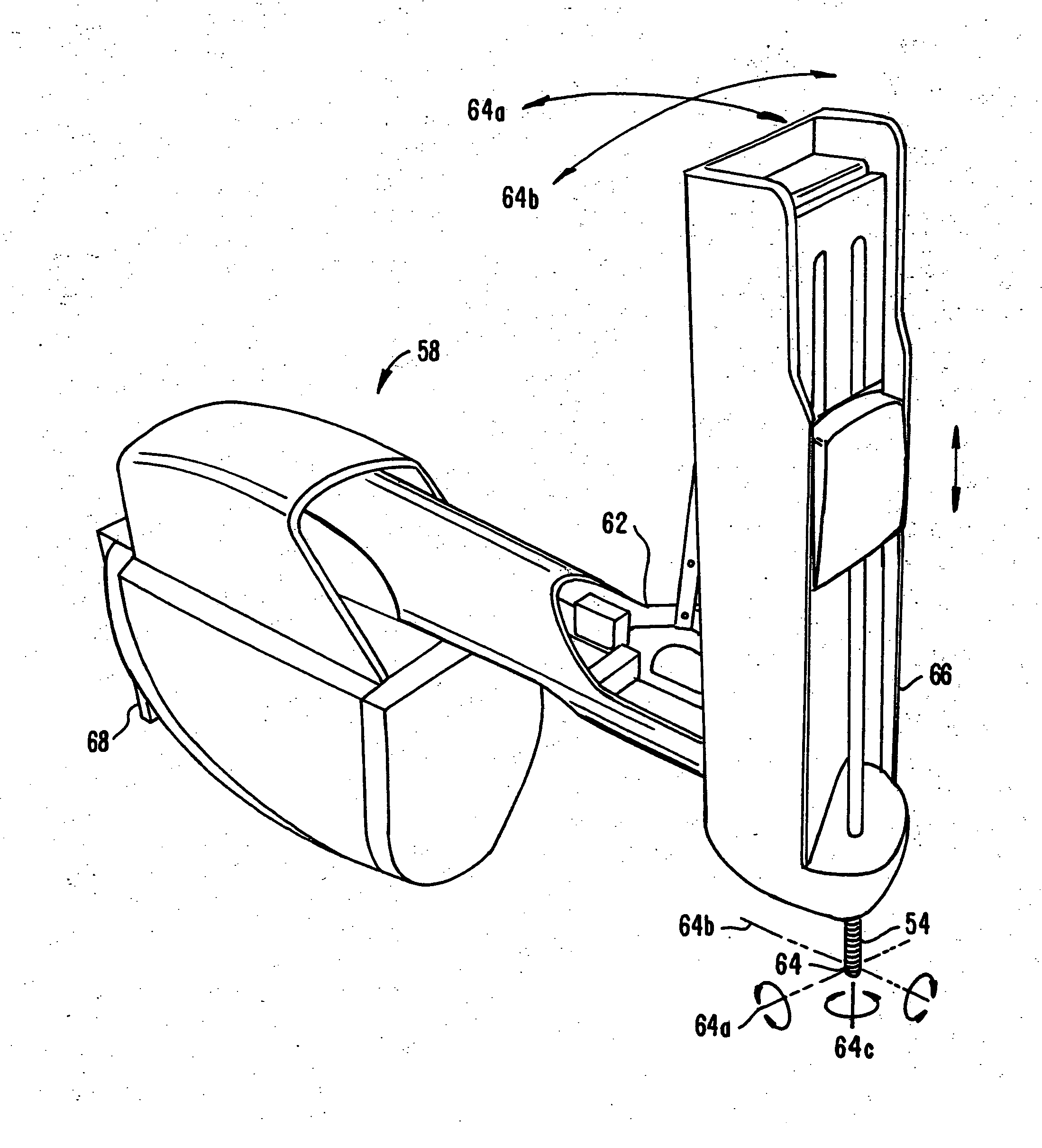
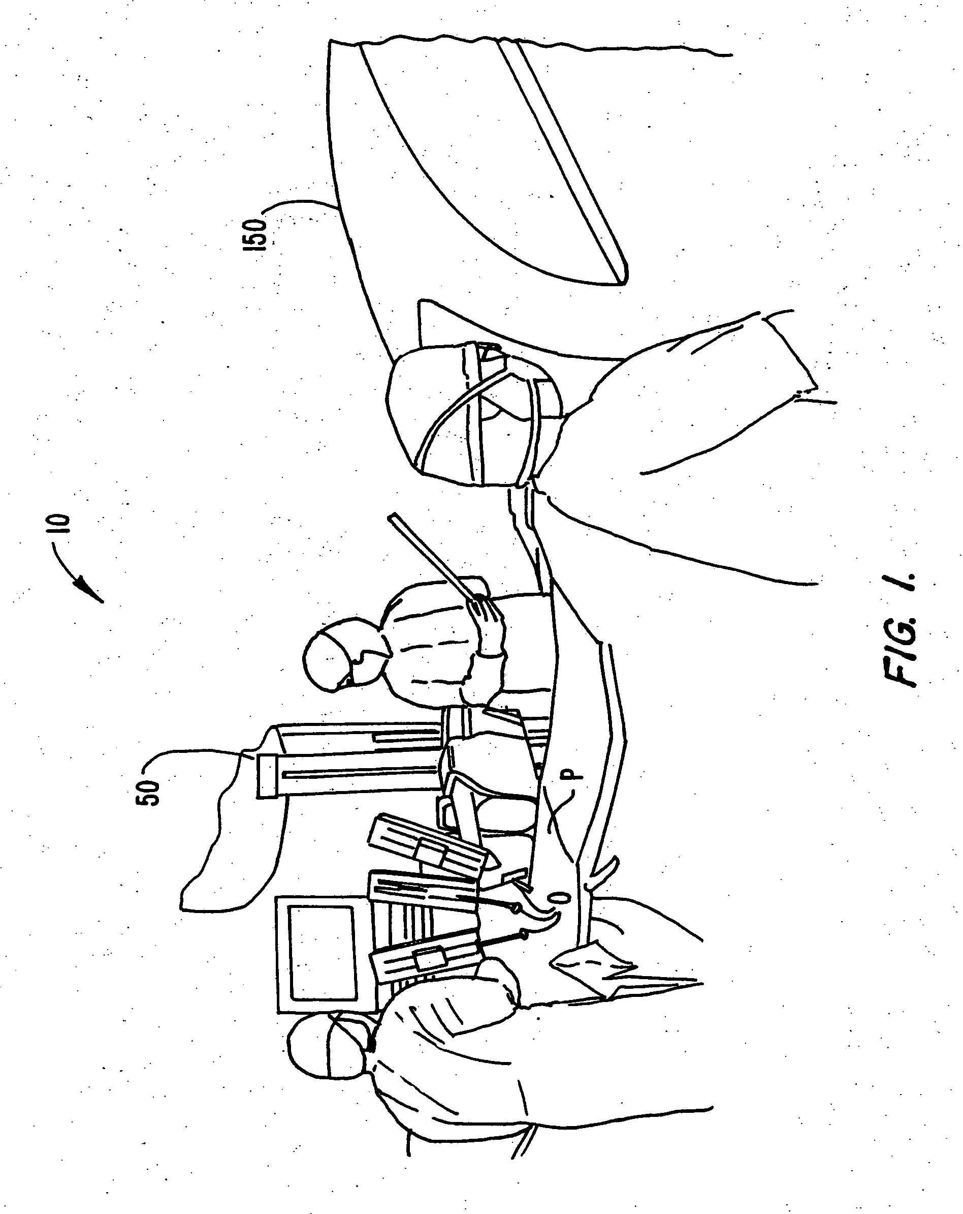
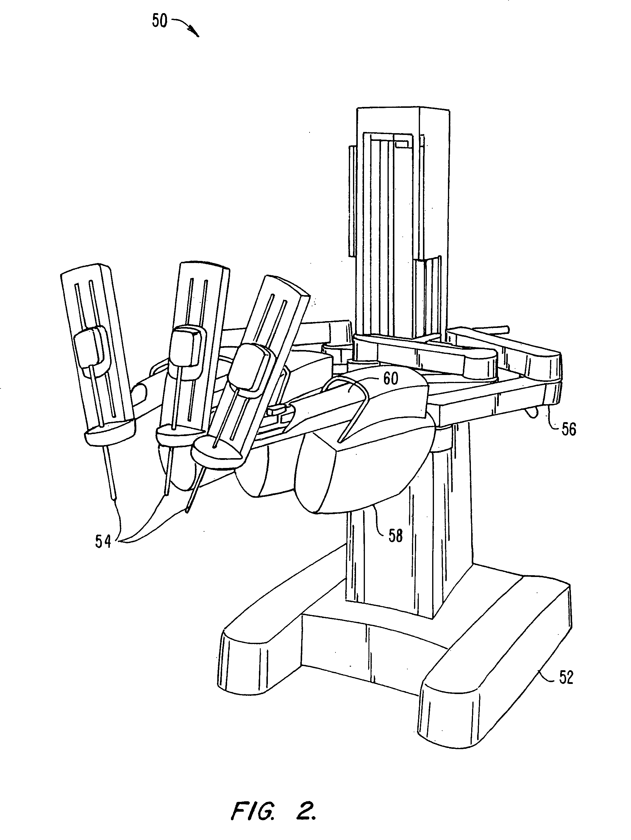
[0041] The present invention provides robotic surgery systems, devices, and methods. Robotic surgery will generally involve the use of multiple robotic arms. One or more of the robotic arms will often support a surgical tool which may be articulated (such as jaws, scissors, graspers, needle holders, microdissectors, staple appliers, tackers, suction / irrigation tools, clip appliers, or the like) or non-articulated (such as cutting blades, cautery probes, irrigators, catheters, suction orifices, or the like). One or more of the robotic arms will often be used to support one or more surgical image capture devices such as an endoscope (which may be any of the variety of structures such as a laparoscope, an arthroscope, a hysteroscope, or the like), or optionally, some other imaging modality (such as ultrasound, fluoroscopy, magnetic resonance imaging, or the like). Typically, the robotic arms will support at least two surgical tools corresponding to the two hands of a surgeon and one op...


PUM


Abstract

Robotic surgical tools, systems, and methods for preparing for and performing robotic surgery include a memory mounted on the tool. The memory can perform a number of functions when the tool is loaded on the tool manipulator: first, the memory can provide a signal verifying that the tool is compatible with that particular robotic system. Secondly, the tool memory may identify the tool-type to the robotic system so that the robotic system can reconfigure its programming. Thirdly, the memory of the tool may indicate tool-specific information, including measured calibration offsets indicating misalignment of the tool drive system, tool life data, or the like. This information maybe stored in a read only memory (ROM), or in a nonvolatile memory which can be written to only a single time. The invention further provides improved engagement structures for coupling robotic surgical tools with manipulator structures.

Description

CROSS-REFERENCES TO RELATED APPLICATIONS [0001] This application is a continuation-in-part of co-pending U.S. patent application Ser. No. 09 / 418,726 filed Oct. 15, 1999, which claims the benefit of U.S. Provisional Patent Appl. No. 60 / 111,713 filed on Dec. 8, 1998, the entirety of which is herein incorporated by reference. This application is also a continuation-in-part of pending U.S. patent application Ser. No. 09 / 406,360 filed Sep. 28, 1999, which is continuation of U.S. patent application Ser. No. 08 / 975,617, filed Nov. 21, 1997 (now U.S. Pat. No. 6,132,368), which claims the benefit of U.S. Provisional Patent Appl. No 60 / 033,321 filed on Dec. 12, 1996, each of which is herein incorporated by reference.BACKGROUND OF THE INVENTION [0002] This invention relates to robotically assisted surgery, and more particularly provides surgical tools having improved mechanical and / or data interface capabilities to enhance the safety, accuracy, and speed of minimally invasive and other robotic...

Claims


Application Information

Patent Timeline
Patent Type & Authority Applications(United States)
IPC IPC(8): A61B17/00A61B19/00A61B19/08G06Q30/02
CPCA61B17/00234Y10T74/20311A61B19/2203A61B19/5212A61B2017/00482A61B2019/082A61B2019/2223A61B2019/223A61B2019/2234A61B2019/2242A61B2019/2292A61B2019/265A61B2019/448A61B2019/4815A61B2019/4894G06Q30/02H01H36/0046H01H85/0056A61B2017/00477A61B19/44Y10S901/41Y10T74/20305A61B18/1445A61B46/13A61B2090/506A61B2090/0818A61B34/71A61B90/361A61B34/37A61B34/35A61B2034/305A61B34/76A61B90/90A61B90/98A61B2090/0803G16H40/63A61B34/30
Inventor TIERNEY, MICHAEL J.COOPER, THOMASJULIAN, CHRISBLUMENKRANZ, STEPHEN J.GUTHART, GARY S.YOUNGE, ROBERT G.
Owner INTUITIVE SURGICAL OPERATIONS INC
Why Eureka
Try Eureka