IOL inserter plunger and body interface

a technology of inserter and plunger, which is applied in the field of ophthalmic surgical devices, can solve the problems of high care to be taken in the handling of the plunger, and trauma to the surrounding tissues of the eye, so as to prevent unintentional separation of the plunger and precise control of the plunger/inserter interface

Inactive Publication Date: 2005-07-07
BAUSCH & LOMB INC
View PDF4 Cites 96 Cited by
  • Summary
  • Abstract
  • Description
  • Claims
  • Application Information

AI Technical Summary

Benefits of technology

[0009] The invention provides an inserter having more precise control of the plunger / inserter interface by providing an inserter with at least one, but preferably a pair of cantilevered projections integrally formed on the shaft of the plunger. The projections are biased radially outwardly of the plunger shaft and are designed to provide a biasing force against the interior wall of the inserter lumen. The inserter body may further include a respective pair of through holes or other features for interacting with the projections to prevent unintentional separation of the plunger from the inserter.

Problems solved by technology

Since IOLs are very small and delicate articles of manufacture, great care must be taken in their handling.
Should the IOL be damaged during delivery into the eye, the surgeon will most likely need to extract the damaged IOL from the eye and replace it with a new IOL, a highly undesirable surgical outcome.
Should the IOL be expelled from the tip too quickly or in the wrong orientation, the surgeon must further manipulate the IOL in the eye possibly resulting in trauma to the surrounding tissues of the eye.
Due to the delicate nature of the IOL, there is a risk that the nurse and / or surgeon will inadvertently damage the IOL and / or incorrectly load the IOL into the inserter device resulting in a failed implantation.
Control of these dynamic forces is therefore of utmost importance or otherwise the IOL may be damaged during delivery due to excessive compressive forces acting thereon.
This may lead to excessive force between the plunger tip and the IOL resulting in possible damage to the IOL and / or uncontrolled release of the IOL from the lumen tip.
Also, the force of the plunger tip may cause the IOL to twist and / or turn as it is moved through the inserter whereby the force between the IOL and the plunger tip and / or the inserter lumen may uncontrollably increase to the point of IOL damage.

Method used


Image

  • IOL inserter plunger and body interface
  • IOL inserter plunger and body interface
  • IOL inserter plunger and body interface

Examples


Embodiment Construction

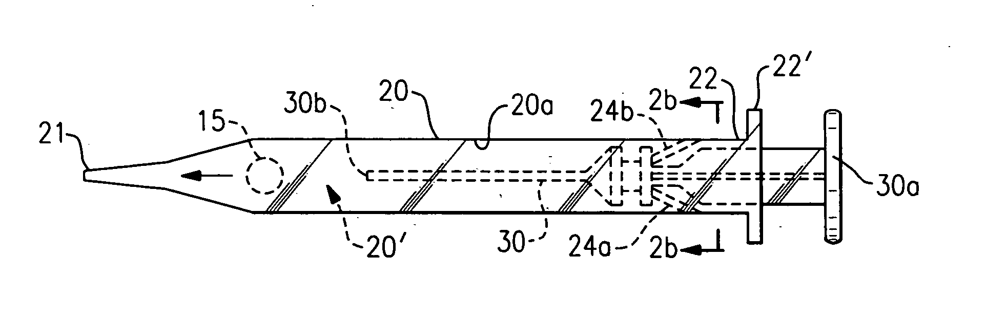
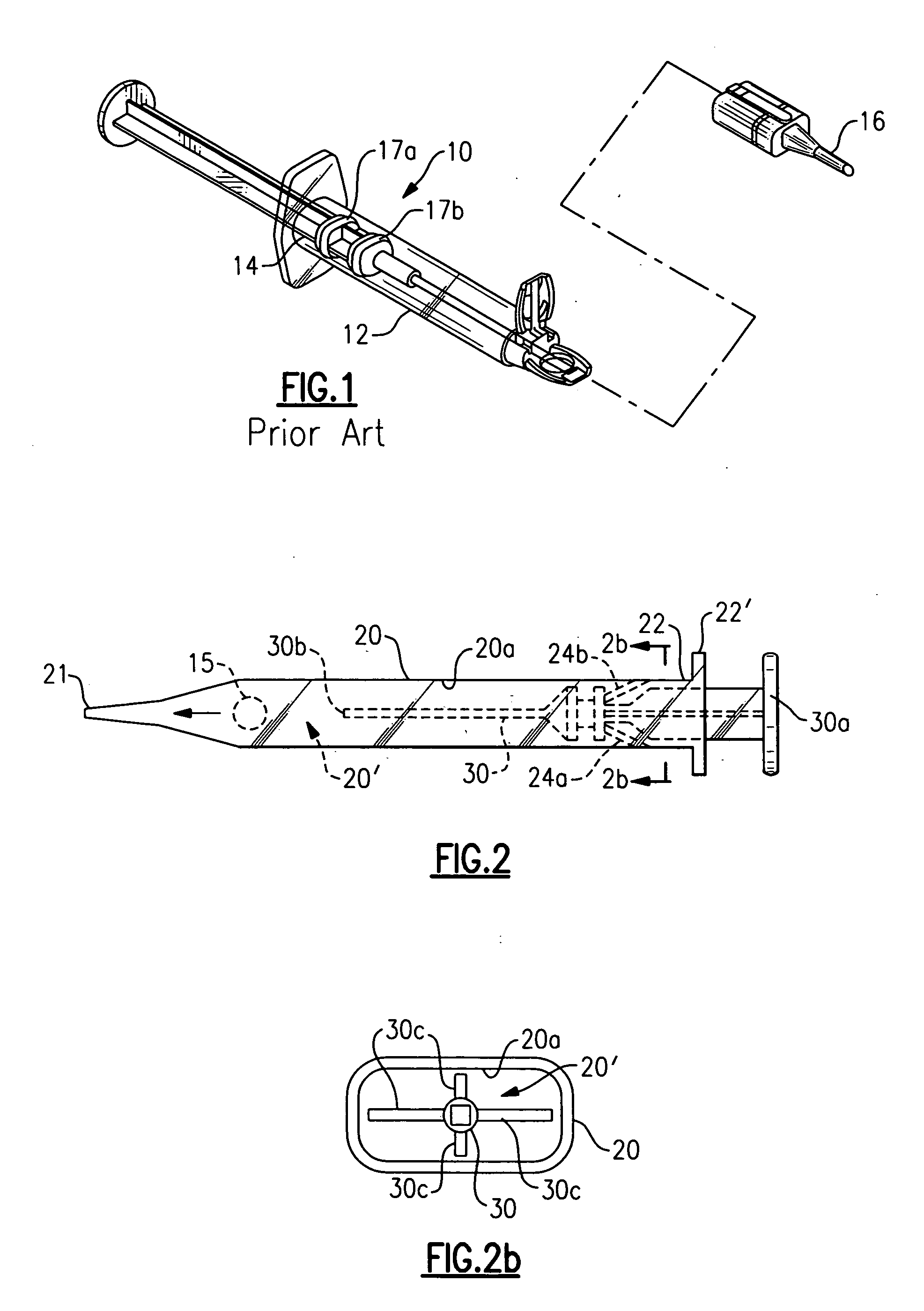
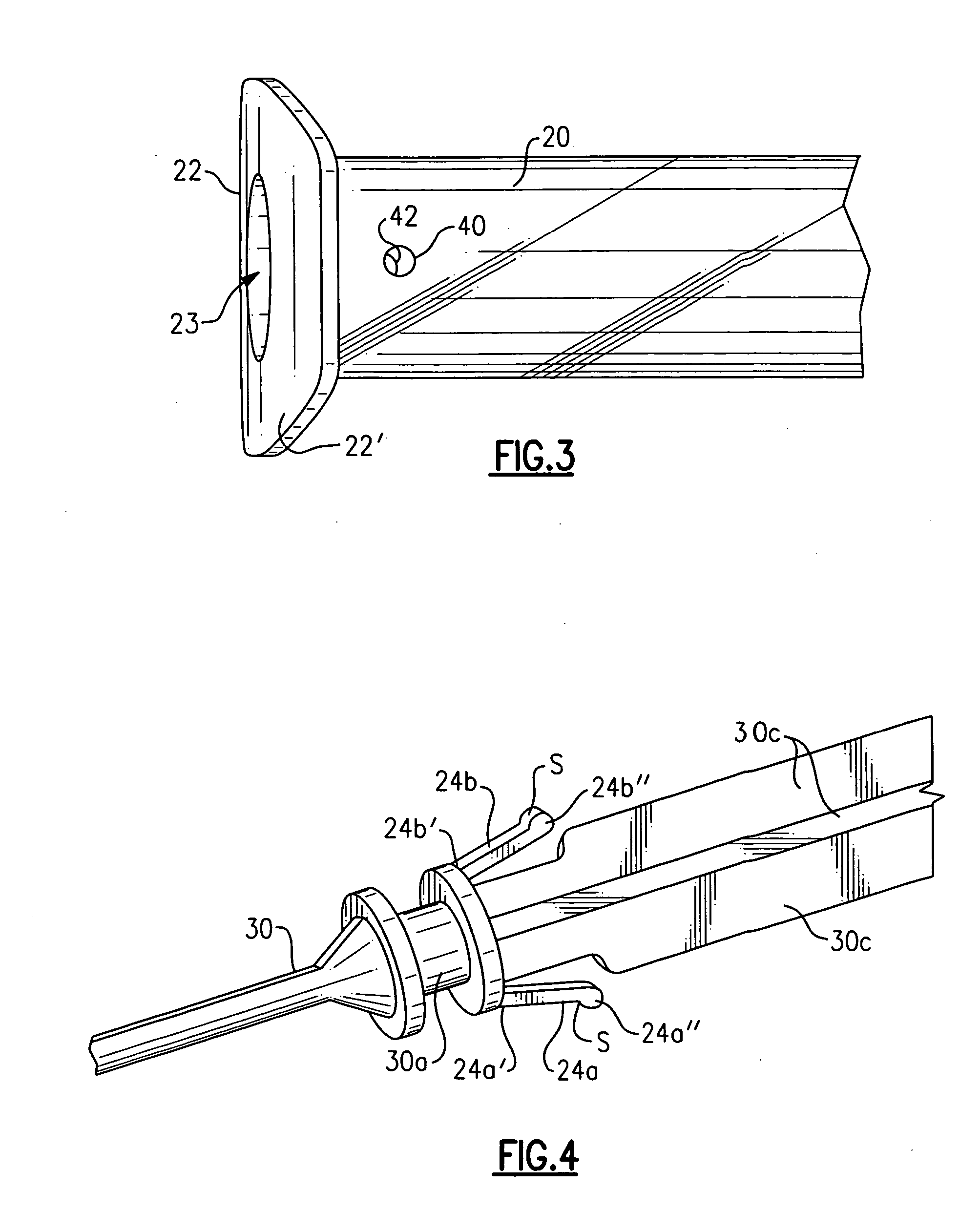
[0016] The present invention is directed towards IOL inserters having a tubular body defining a longitudinal passageway or lumen extending from a proximal end to a distal tip of the inserter, and a plunger component which telescopes in the open proximal end of the tubular body. A prior art inserter device 10 is seen in FIG. 1 to include a tubular body 12 having an open proximal end 14 and opposite distal tip 16 which is inserted into an incision in an eye for passing an IOL through the inserter, out tip 16 and into the eye. To control movement of the plunger within the body, the prior art device uses one or more rubber O-rings 17a, 17b which provide friction between the plunger and inside wall of the body. O-rings are separate pieces that require direct manual attachment to the plunger component thereby increasing the cost of manufacture. Furthermore, prior art device 10 does not include any feature to prevent unintentional retraction and / or disengagement of the plunger with respect...


PUM


Abstract

An injector body and plunger for injecting an IOL into an eye includes one or more cantilevered projections attached to the plunger shaft to provide a resistive force between the plunger and injector body. Detents may be strategically positioned along the injector body for engaging with the free ends of the projections to selectively locate the longitudinal position of the plunger relative to the body.

Description

BACKGROUND OF THE INVENTION [0001] The present invention relates to ophthalmic surgical devices. More particularly, the present invention relates to a device for inserting an intraocular lens (IOL) into an eye. [0002] IOLs are artificial lenses used to replace the natural crystalline lens of the eye when the natural lens has cataracts or is otherwise diseased. IOLs are also sometimes implanted into an eye to correct refractive errors of the eye in which case the natural lens may remain in the eye together with the implanted IOL. The IOL may be placed in either the posterior chamber or anterior chamber of the eye. IOLs come in a variety of configurations and materials. Some common IOL styles include the so-called open-looped haptics which include the three-piece type having an optic and two haptics attached to and extending from the optic; the one-piece type wherein the optic and haptics are integrally formed (e.g., by machining the optic and haptics together from a single block of m...

Claims


Application Information

Patent Timeline
Patent Type & Authority Applications(United States)
IPC IPC(8): A61F2/16
CPCA61F2/167
Inventor RATHERT, BRIAN D.
Owner BAUSCH & LOMB INC
Why Eureka
Try Eureka