Method for spray-coating a medical device having tubular wall such as a stent

a technology of tubular wall and spray coating, which is applied in the direction of liquid spraying plant, packaging goods, chemical/physical/physico-chemical processes, etc., can solve the problem of fixed ratio between the thickness of coating placed on the inner the thickness placed on the outer surface of the tubular wall created by a conventional method, and cannot be varied

Inactive Publication Date: 2005-07-07
BOSTON SCI SCIMED INC
View PDF9 Cites 51 Cited by
  • Summary
  • Abstract
  • Description
  • Claims
  • Application Information

AI Technical Summary

Benefits of technology

[0010] Furthermore, in the method of the present invention, the core wire can be kept free of the coating formulation by, for example, using two bobbins, wherein one is feeding the core wire through the tubular wall and the other is winding the core wire. Also, in the method of the present invention, a pair of deflector plates can be used to direct the charged coating formulation.

Problems solved by technology

When a tubular wall, such as a stent, having openings therein is coated by conventional methods, it has been extremely difficult to coat only the inner surface of a tubular wall without coating the outer surface and vice versa.
Also, the ratio of coating thickness placed on the inner surface of the tubular wall and placed on the outer surface of the tubular wall created by a conventional method is fixed and cannot be varied.
Accordingly, this ratio cannot be controlled.
Also, conventional coating methods lack the ability to coat a tubular wall so that the coating thickness along the longitudinal axis of the tubular wall is varied.

Method used


Image

  • Method for spray-coating a medical device having tubular wall such as a stent
  • Method for spray-coating a medical device having tubular wall such as a stent
  • Method for spray-coating a medical device having tubular wall such as a stent

Examples


Embodiment Construction

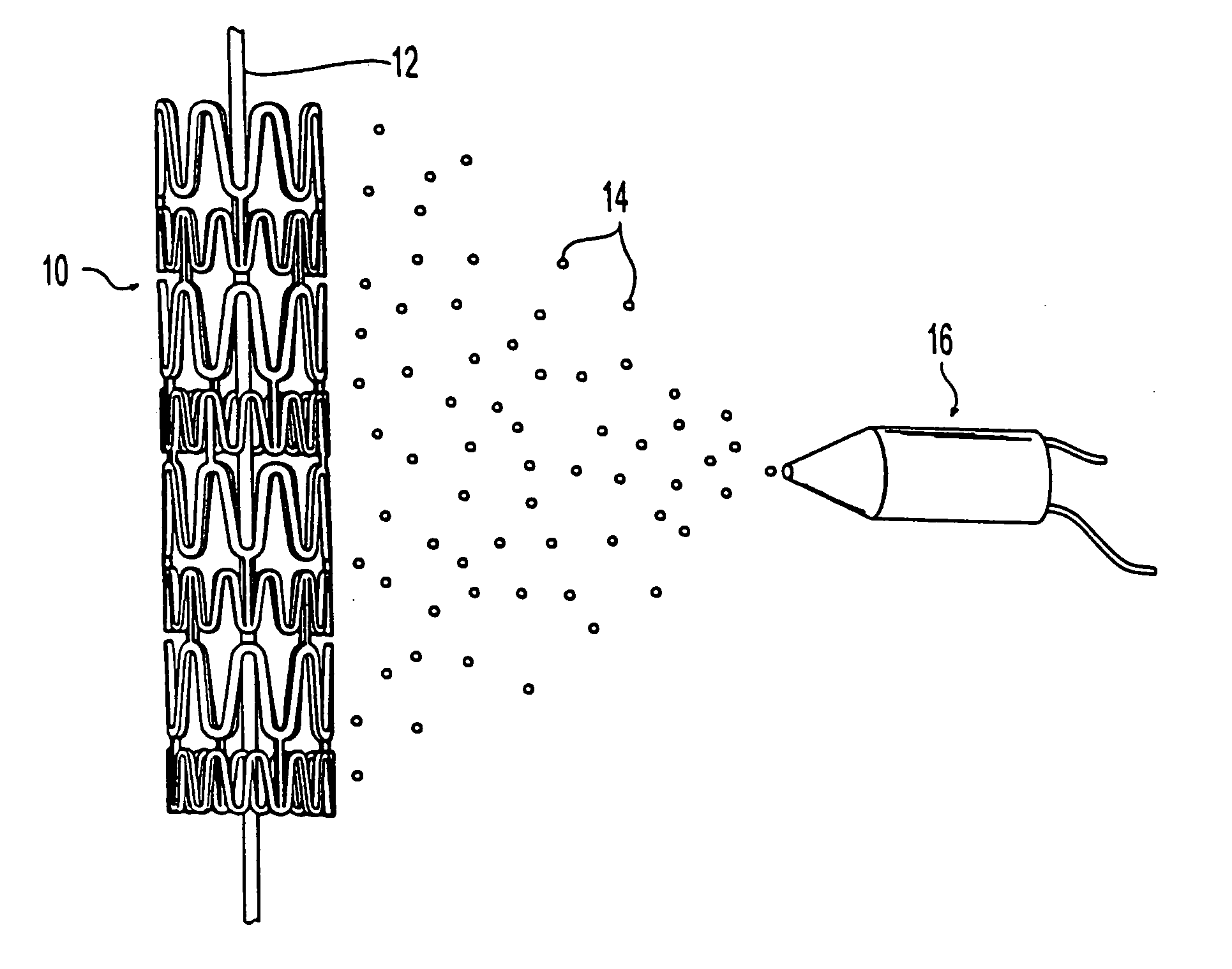
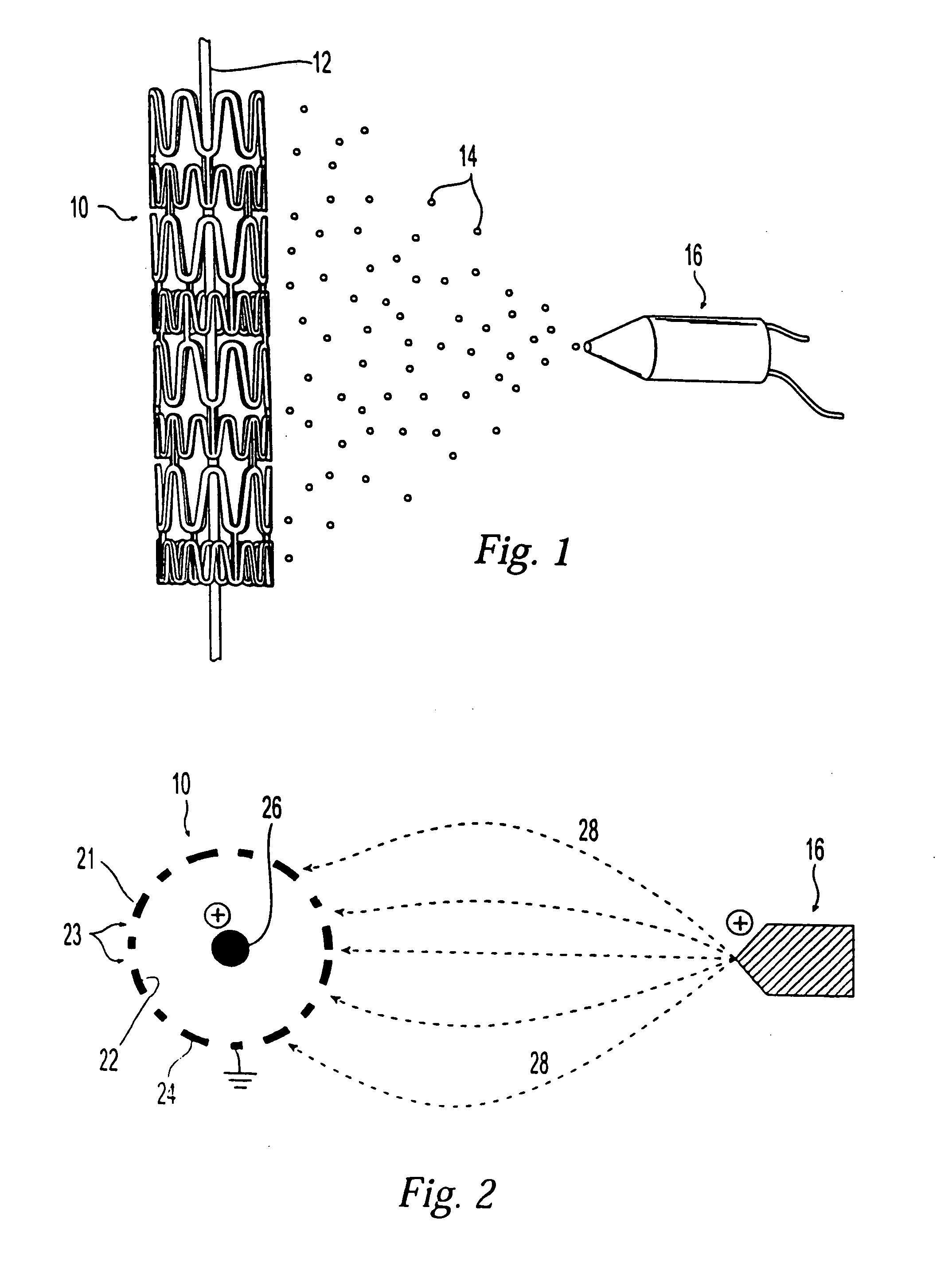
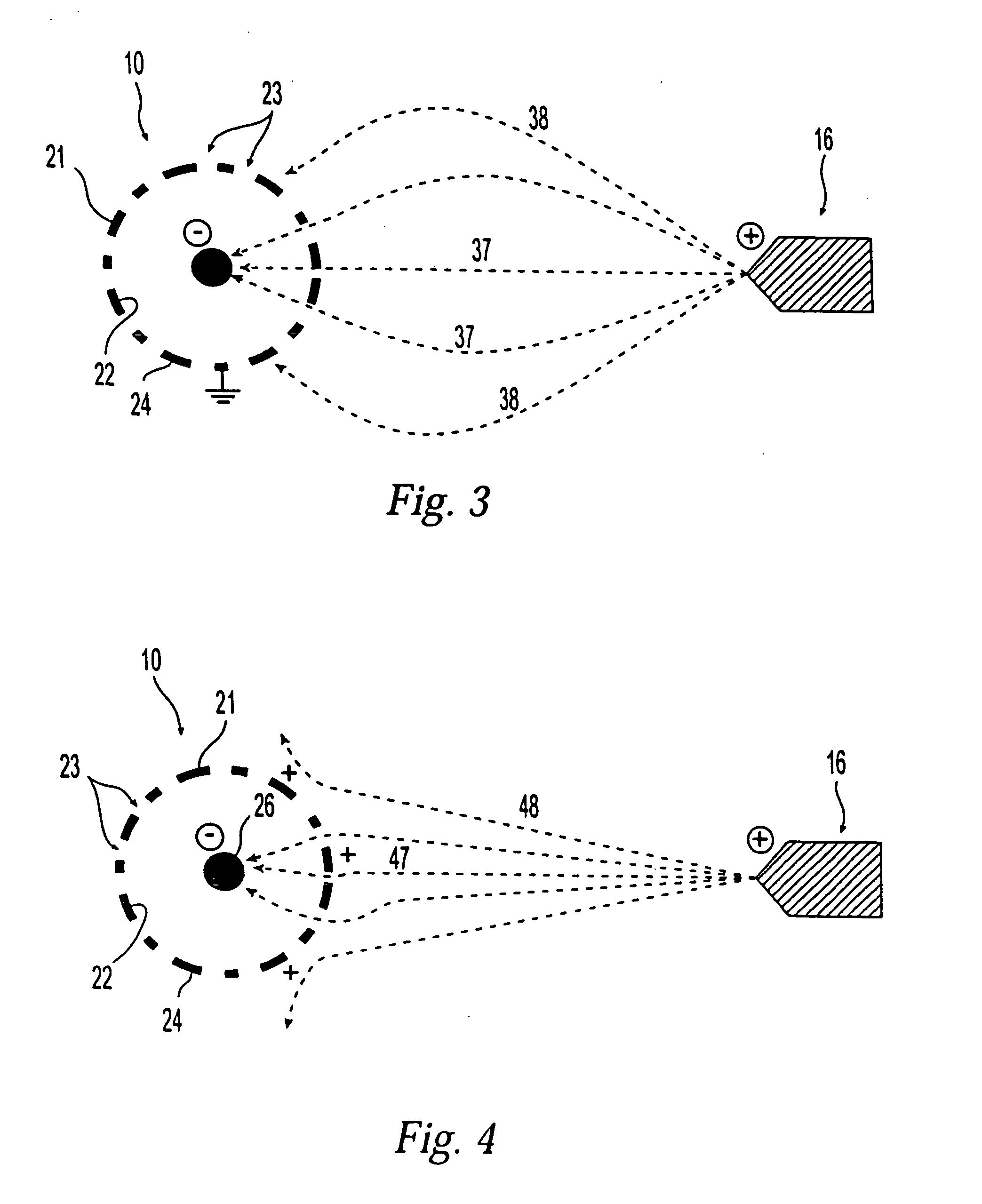
[0017] In the method of the present invention, the amount of a coating formulation that is applied to a surface of a stent or tubular wall of a medical device is adjusted by employing the principles of electro-assisted spraying and a core wire located through the stent or tubular wall. The term “tubular wall” refers to a wall having a certain thickness to configured in a shape of a tube or tubular structure. Such tubular structure may have a cross-section other than circle, such as an oval or square. In conventional electro-assisted spraying techniques, an electrically charged coating formulation is sprayed or applied to the surface of the device to be coated. The device is usually grounded or negatively charged. Since the coating formulation is a poor conductor, part of the electrical charge of the coating formulation is unable to escape. Therefore, those portions of the device surface that are coated with the coating formulation will have a higher potential than uncoated regions, ...


PUM

PropertyMeasurementUnit
sizeaaaaaaaaaa
diameteraaaaaaaaaa
conductiveaaaaaaaaaa

Abstract

A method for electrostatic spray-coating a medical device having a tubular wall, such as a stent, having an inner surface, an outer surface and openings therein. The tubular wall is grounded or electrically charged, and an electrically charged conductive core wire is located axially through the center of the stent. An electrical potential is applied to the conductive core wire to impart an electrical charge to the conductive core wire. The tubular wall is exposed to an electrically charged coating formulation, and the electrically charged coating formulation is deposited onto a portion of the tubular wall to form a coating. The electrical potentials of the conductive core wire and tubular wall can be repeatedly alternated.

Description

FIELD OF THE INVENTION [0001] The invention relates generally to a method for coating a stent or a medical device having a tubular wall. More particularly, the invention is directed to a method for electrostatic spray-coating a stent or a medical device having a tubular wall. BACKGROUND OF THE INVENTION [0002] Medical devices, such as implantable stents, have been coated with a coating comprising a biocompatible polymer to reduce adverse physiological reactions, such as restenosis, caused by uncoated surfaces of medical devices inserted or implanted in patient's body. Also, the coating can incorporate a biologically active material. For example, implanted stents have been used to carry medicinal agents, such as thrombolytic agents. See, U.S. Pat. No. 6,099,562 to Ding et al. U.S. Pat. No. 5,879,697 to Ding et al., Pinchuk to U.S. Pat. No. 5,092,877, U.S. Pat. No. 5,304,121 to Sahatjian. [0003] Such coatings have been applied to the surface of a medical device by various methods, e.g...

Claims


Application Information

Patent Timeline
Patent Type & Authority Applications(United States)
IPC IPC(8): A61F2/06A61L27/34A61L29/08A61L31/10B05B5/08B05B5/12B05D1/04
CPCA61L27/34A61L29/085B05D1/045B05B5/087B05B5/12A61L31/10
Inventor WEBER, JANKOCUR, GORDON JOHN
Owner BOSTON SCI SCIMED INC
Why Eureka
Try Eureka