Mobile chafing dish apparatus

a chafing dish and mobile technology, applied in the field of mobile or portable devices, to achieve the effect of convenient movemen

a chafing dish and mobile technology, applied in the field of mobile or portable devices, to achieve the effect of convenient movemen

US20050150395A1Inactive Publication Date: 2005-07-14OLEKAIBE BENSON A +1

Image

  • Mobile chafing dish apparatus
  • Mobile chafing dish apparatus
  • Mobile chafing dish apparatus

Examples


Embodiment Construction

[0030] With reference to the drawings, a new and improved mobile chafing dish apparatus embodying the principles and concepts of the present invention will be described.

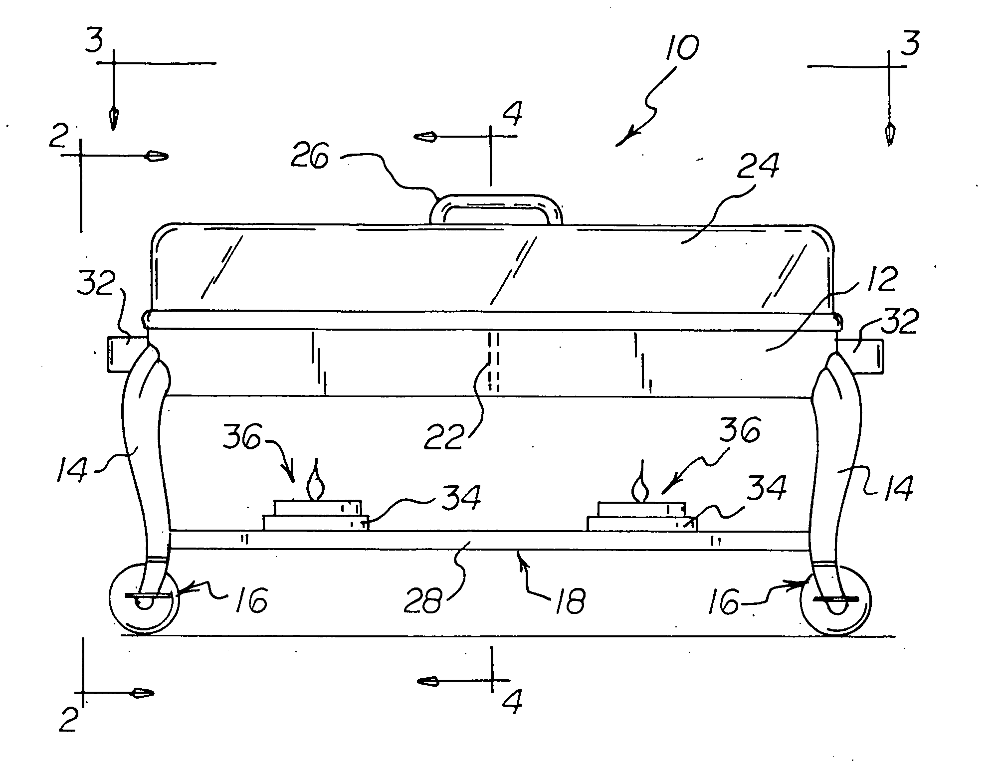
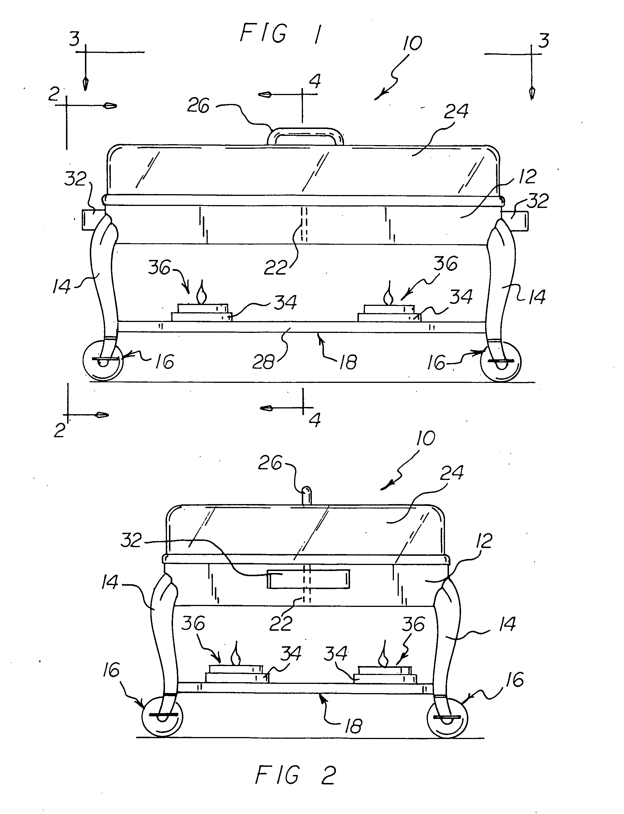
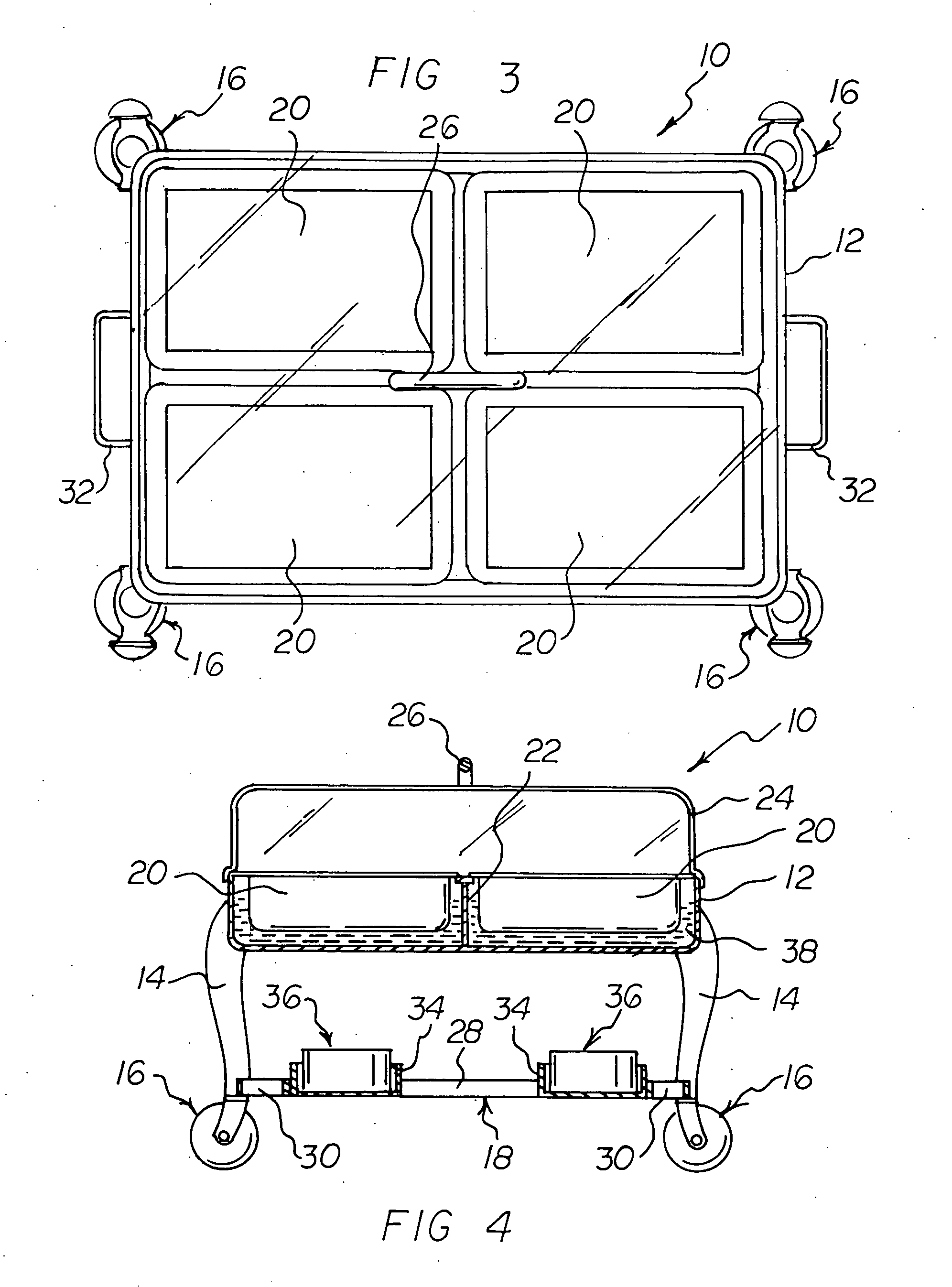
[0031] Turning to FIGS. 1-5, there is shown a preferred embodiment of the mobile chafing dish apparatus of the invention generally designated by reference numeral 10. In the preferred embodiment, mobile chafing dish apparatus 10 includes a dish-support pan 12, a plurality of legs 14 connected to the dish-support pan 12, and wheel assemblies 16 connected to respective distal ends of each of the legs 14. A fuel-support pan assembly 18 is connected to the plurality of legs 14, and a plurality of chafing dishes 20 are supported by the dish-support pan 12.

[0032] Preferably, the dish-support pan 12 further includes a central dish support member 22 extending upward from a central bottom portion of the dish-support pan 12. The dish-support pan 12 includes pan handles 32 located at ends of the dish-support pan 12. A cover 2...


PUM


Abstract

A mobile chafing dish apparatus includes a dish-support pan, a plurality of legs connected to the dish-support pan, and swivel caster wheel assemblies connected to respective distal ends of each of the legs. A fuel-support pan assembly is connected to the plurality of legs, and a plurality of chafing dishes are supported by the dish-support pan. With the mobile chafing dish apparatus of the invention, the mobile chafing dish apparatus can be easily moved along a table top surface by simply pulling on or pushing the apparatus. The dish-support pan includes pan handles located at ends of the dish-support pan. A transparent cover is supported by the dish-support pan. Preferably, fuel-burner-reception walls are supported by the fuel-support pan assembly. Fuel burners are received in regions defined by the respective fuel-burner-reception walls.

Description

CROSS-REFERENCE TO RELATED APPLICATION [0001] This application claims priority based upon my copending Provisional Application Ser. No. 60 / 535,636, filed Jan. 12, 2004.BACKGROUND OF THE INVENTION [0002] 1. Field of the Invention [0003] The present invention relates generally to devices for heating food and, more particularly, to mobile or portable devices especially adapted for heating food. [0004] 2. Description of the Prior Art [0005] Mobile or portable devices for heating food are well known in the art. In this respect, throughout the years, a number of innovations have been developed relating to mobile or portable devices for heating food, and the following U.S. patents are representative of some of those innovations: U.S. Pat. Nos. 2,520,543, 4,665,888, 4,739,580, 6,267,111, and 6,591,831. [0006] More specifically, each of U.S. Pat. Nos. 2,520,543, 4,665,888, 6,267,111, and 6,591,831 discloses a mobile device for heating foods. Each of the respective mobile devices has wheels t...

Claims


Application Information

Patent Timeline
14 Jul 2005
Publication
US20050150395A1
IPC
A23C15/04; A47J27/18; A47J36/26
CPC
A47J27/18; A47J36/26; A47J36/2405
Inventors
OLEKAIBE, BENSON A.; OLEKAIBE, ESTHER C.