Handle apparatus for luggage case

a luggage case and handle technology, applied in the field of rolling luggage cases, can solve the problems of user problems, affecting the use of the luggage case, and putting a certain amount of strain on the user's wrist, elbow, and shoulder joints, and achieve the effect of minimizing the weight of the luggage case at the front of the hand

Inactive Publication Date: 2005-07-14
INVENTIVE TRAVELWARE
View PDF25 Cites 14 Cited by
  • Summary
  • Abstract
  • Description
  • Claims
  • Application Information

AI Technical Summary

Benefits of technology

[0014] Another ergonomic feature of the invention is that the cantilevered handle grip is attached to the handle arm such that a slight resilient force is applied to the hinge, causing the grip to rotate or hinge in a downward direction, while the luggage case is being pulled. This force acts to distribute the weight of the luggage uniformly across the fingers and palm of the user's hand. In this manner, a concentration of the luggage case's weight at the front of the hand is minimized.

Problems solved by technology

Although the “U” shaped or double-tube design used in current luggage cases is primarily a legacy of the collapsible luggage carts, the redundant design does not appear to be a functional necessity.
These grip designs present several problems for the user.
One problem is that in order for a user to grasp the grip handle, the user must rotate or twist his or her arm approximately 90° from the arm's natural position, hanging at the user's side.
This twisting motion puts a certain amount of strain on the user's wrist, elbow, and shoulder joint, and can cause discomfort when pulling heavy loads or loads over a long distance.
Another problem is that all rolling luggage systems have a tendency to tip over when the luggage is rolled over uneven ground.
Unfortunately, current handle grip designs which place the user's hand and arm in an unnatural twisted position, actually exacerbate the tipping problem because a person's arm has less strength in an unnatural position.
Thus, the luggage is more likely to tip over.
Tipping also causes another problem.
If the user cannot efficiently counteract the tipping motion while the luggage is being rolled, the luggage may be dragged, rather than rolled, causing excessive wear to an outside portion of the wheel.
This unwanted action causes the wheel to develop a flat spot, which will eventually require that it be replaced.
It is generally known that wheel replacement or repair is a common maintenance expense in the use of wheeled luggage.
Unfortunately, since the handle is not integral with the preexisting “U” shaped handle, the design introduces a substantial instability problem which contributes to the wheel damage described above.
The add-on handle is also not easy to use, and prone to being lost or damaged.

Method used


Image

  • Handle apparatus for luggage case
  • Handle apparatus for luggage case
  • Handle apparatus for luggage case

Examples


Embodiment Construction

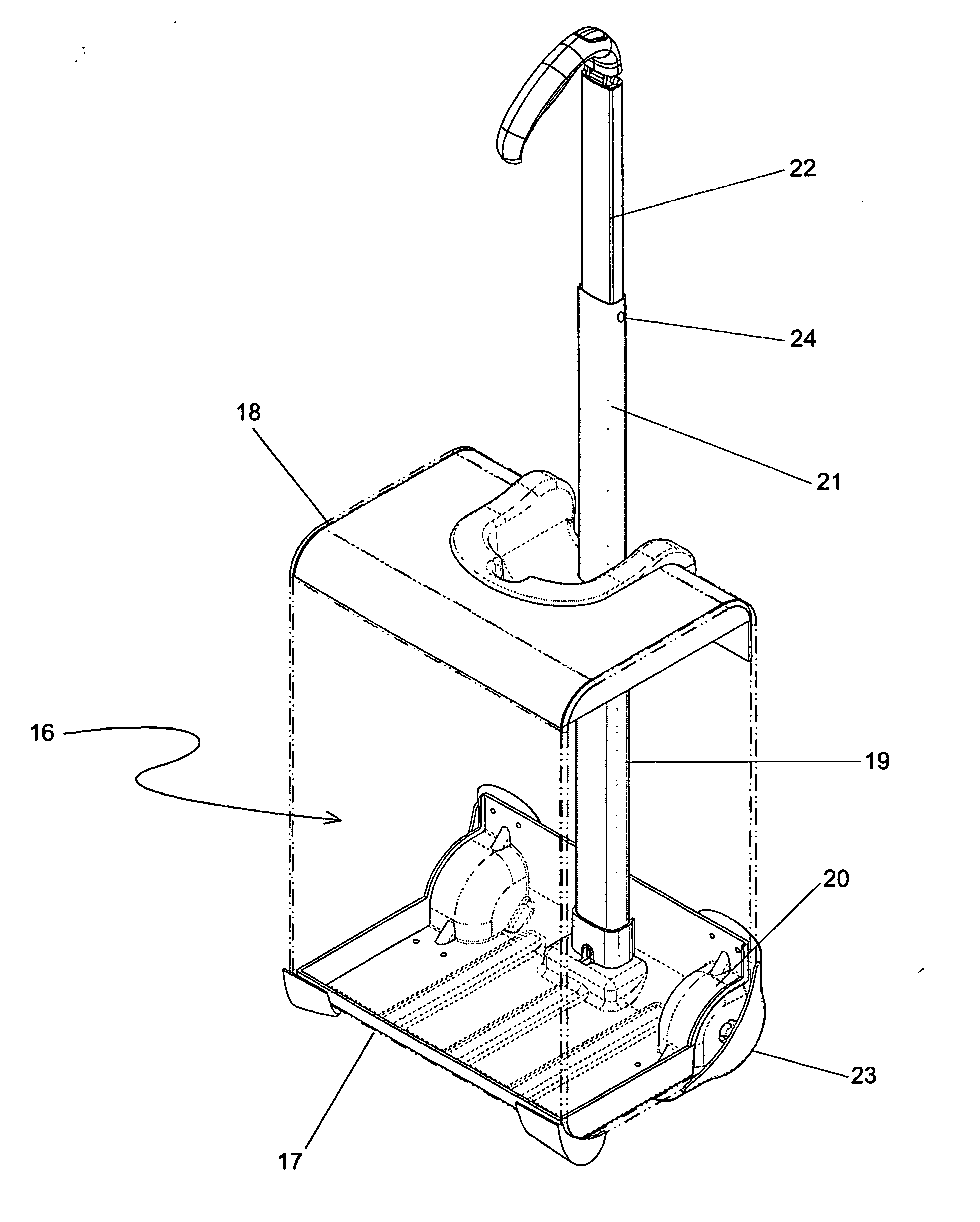
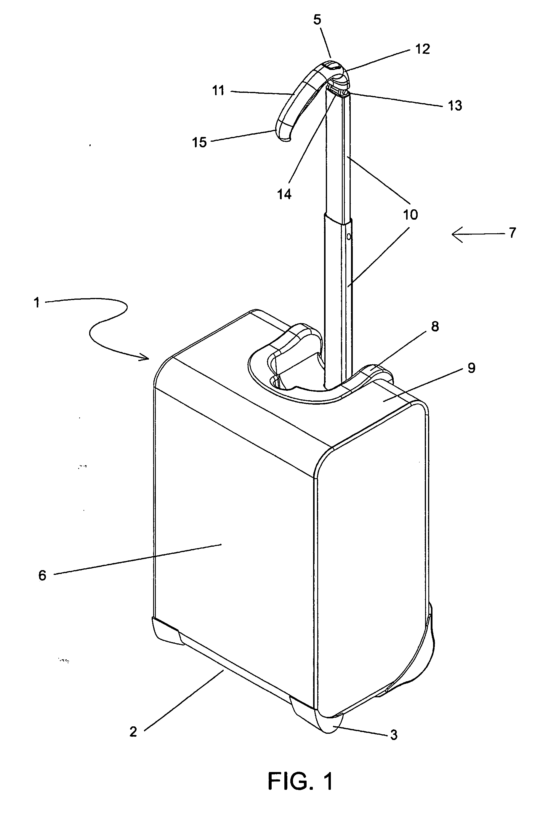
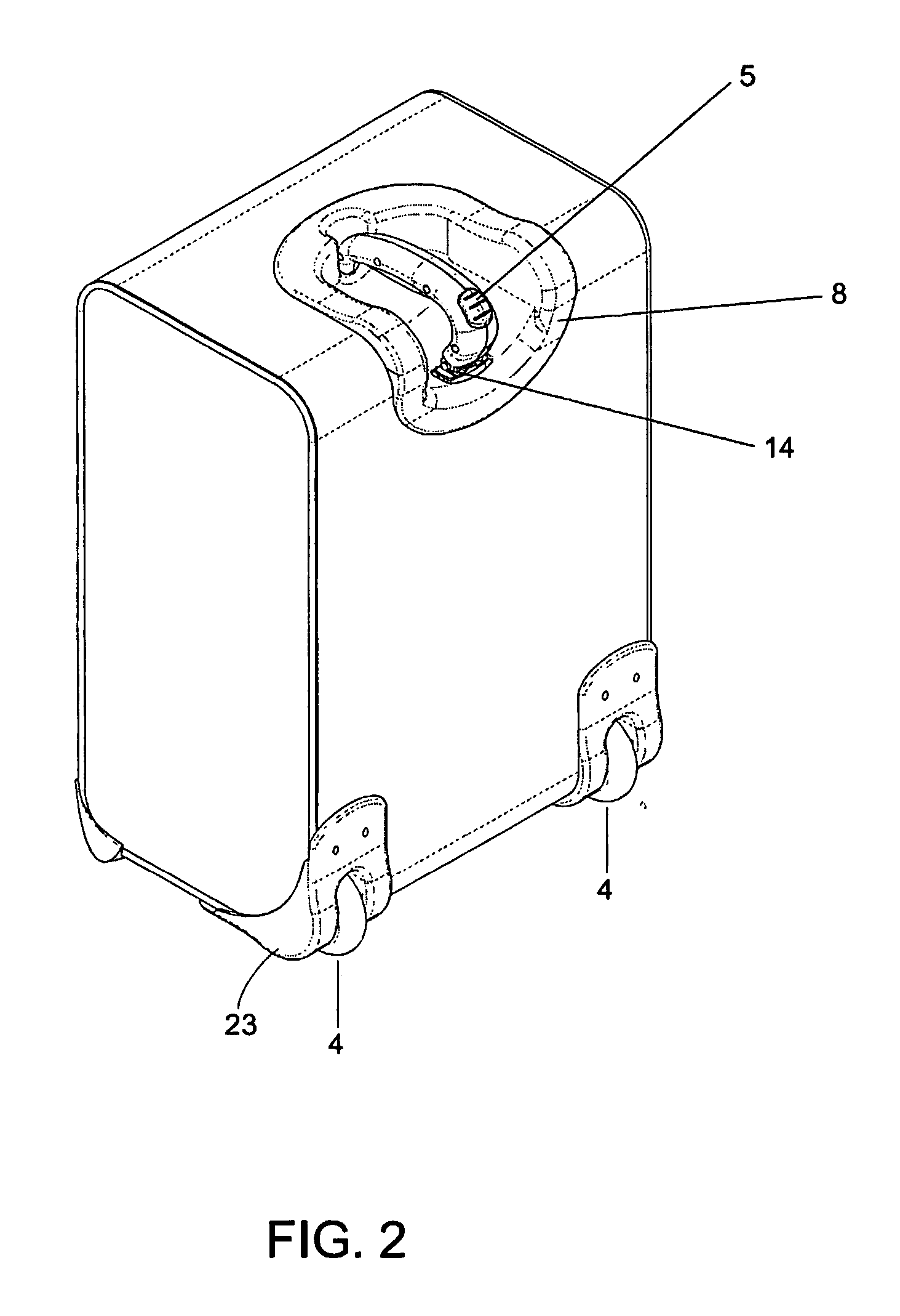
[0022] The present invention is generally described in connection with FIGS. 1, 2 and 3. FIG. 1 illustrates a perspective view of a wheeled luggage case 1 which is tipped up on a bottom end 2 and is resting in a vertical position on a pair of bottom studs 3 and on a pair of wheels 4, which are adjacent to the bottom studs 3. The axle of each wheel 4, is in axial alignment with the other wheel, and each wheel and its corresponding axle is rotatably mounted to a luggage frame 16. A luggage compartment 6 is disposed around and attached to the luggage frame 16. A handle assembly 7 extends through a handle grip cradle 8 disposed within an upright end 9 of the luggage case 1. The handle assembly 7 includes a single telescoping handle arm assembly 10, which is depicted in its extended position. The handle assembly also contains an integral cantilevered handle grip 11 which is connected at a back grip end 12 to a top end 13 of the telescoping handle arm assembly 10 by means of a hinge assem...


PUM


Abstract

A wheeled luggage case (1) has a single telescoping handle arm assembly (10) and a cantilevered handle grip (11) which is rotatably attached to the top end (13) of the handle arm assembly, such that the plane of rotation of the grip is approximately parallel to the rolling direction of the luggage case. The cantilevered handle grip (11) rotates from a position approximately perpendicular to the telescoping handle arm assembly (10) to a position approximately 30° below the horizontal, and a resilient element is provided which urges the grip to rotate downwardly while in use. The invention provides an ergonomically comfortable wheeled luggage case by allowing the user to grasp the grip in a natural position and, simultaneously, increasing the amount of leverage available to prevent the luggage case from tipping over when it is rolled over uneven ground. Further, the resilient element distributes the weight of the luggage case evenly across the user's hand.

Description

FIELD OF INVENTION [0001] The present invention relates generally to the field of rollable luggage cases and to other types of cases. BACKGROUND OF INVENTION [0002] Most current wheeled luggage systems use a similar design consisting of two telescoping tubes or arms attached to the back side of the luggage compartment and a handle grip connected across the top of the tubes to form an upside-down “U” shaped steering handle. Two wheels are usually provided on opposite sides of the bottom back side of the luggage compartment. In operation a user extends the telescoping tubes out of the luggage compartment by pulling upward on the handle grip, tilts the luggage to a comfortable and stable position, and rolls the luggage along its wheels. When the user stops moving, the luggage may be tilted upright on its bottom end, by normally resting the luggage on a “bottom stud” adjacent to the wheels. This type of rollable luggage has become known as “Uprights,”“Trolley Cases,” or “Vertical Pullma...

Claims


Application Information

Patent Timeline
Patent Type & Authority Applications(United States)
IPC IPC(8): A45C5/02A45C5/14A45C13/22A45C13/26
CPCA45C5/02A45C5/14A45C13/22Y10T16/451A45C2013/267Y10T16/455A45C13/262
Inventor COSTA, RICHARD ARODGERS, GLENN H. JR.HAN, NOAH M.YANG, SUNG O.
Owner INVENTIVE TRAVELWARE
Why Eureka
Try Eureka