One-piece fluid nozzle

US20050150981A1Inactive Publication Date: 2005-07-14CARLISLE FLUID TECH INC
54 Cites 3 Cited by

Patent Information

Authority / Receiving Office
US · United States
Current Assignee / Owner
Publication Date
2005-07-14
Estimated Expiration
Not applicable · inactive patent

Smart Images

  • Figure 1
    Figure 1
  • Figure 2
    Figure 2
  • Figure 3
    Figure 3
Patent Text Reader

Abstract

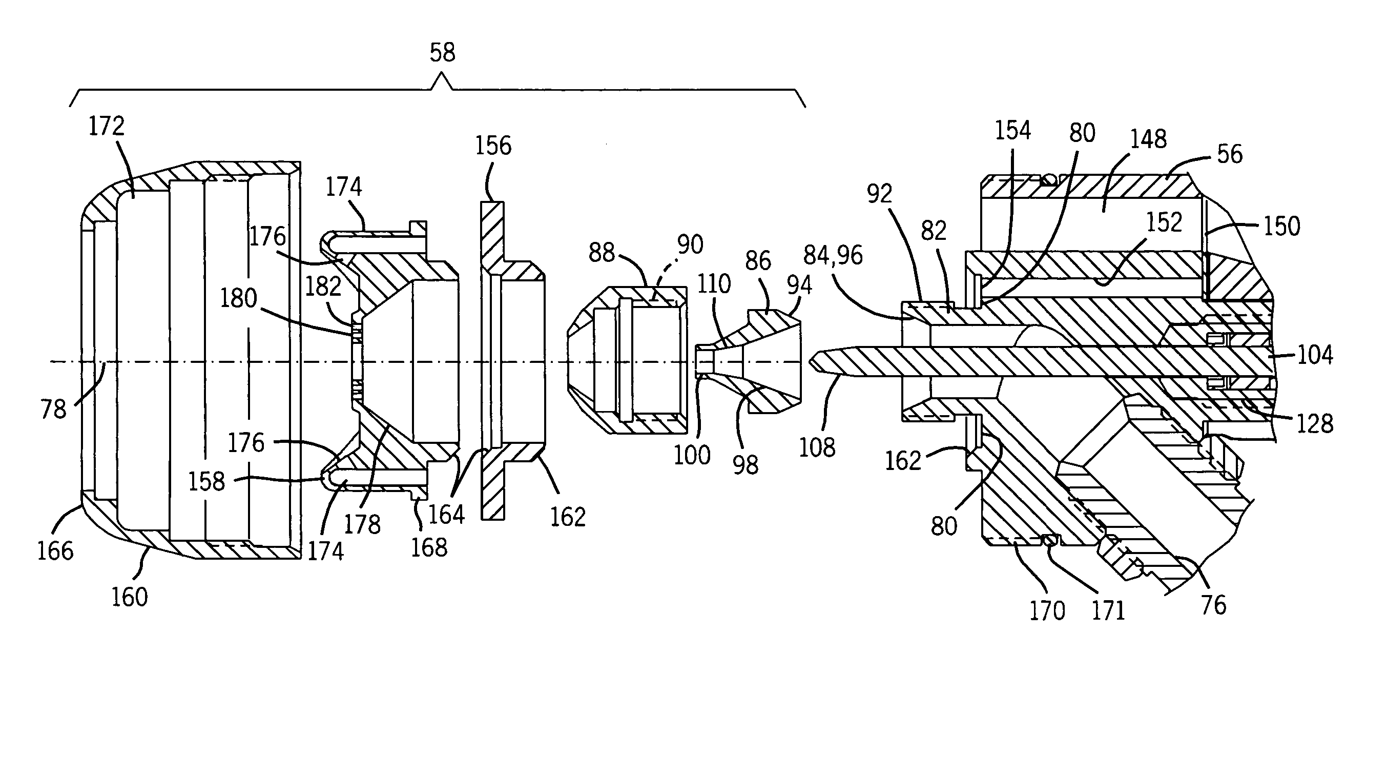
A system and method for reducing fluid drainage into air passageways of a spray device during disassembly. The present technique provides an internally mountable fluid nozzle having a fluid inlet, a fluid exit, and a converging central passageway extending substantially between the fluid inlet and the fluid exit. Accordingly, the internally mountable fluid nozzle has a relatively small internal volume, which reduces the amount of fluid that can be spilled during disassembly of the spray device. The present technique also provides a section of the spray device having an air passageway with an air exit, and a protrusive fluid passageway with a fluid exit in a protrusive offset position from the air exit. The internally mountable fluid nozzle can be mounted to the section in fluid communication with the protrusive fluid passageway, such that fluid spillage or drainage during disassembly does not flow into the air passageway. A spray formation section also may be coupled to the section, such that an internal cavity of the spray formation section is disposed about the internally mountable fluid nozzle.
Need to check novelty before this filing date? Find Prior Art

Description

CROSS-REFERENCE TO RELATED APPLICATION

[0001] The following is a continuation of application Ser. No. 10 / 377,011, filed on Feb. 28, 2003.BACKGROUND OF THE INVENTION

[0002] The present technique relates generally to spray systems. More specifically, a technique is provided for reducing fluid drainage into internal passageways and components of a spray device during disassembly.

[0003] Spray devices generally have several sections and passageways that operate to create a spray, such as an atomized fluid spray. In many situations, it may be desirable to disassemble the spray device for cleaning, servicing, parts replacement, or other reasons. Unfortunately, residual fluid in the spray device often drains into adjacent air passageways and onto other portions of the spray device during the disassembly process. This fluid drainage is partially attributed to the close proximity of fluid and air passageways, particularly the air passageways extending around a fluid nozzle. The internal volu...

Examples

Embodiment Construction

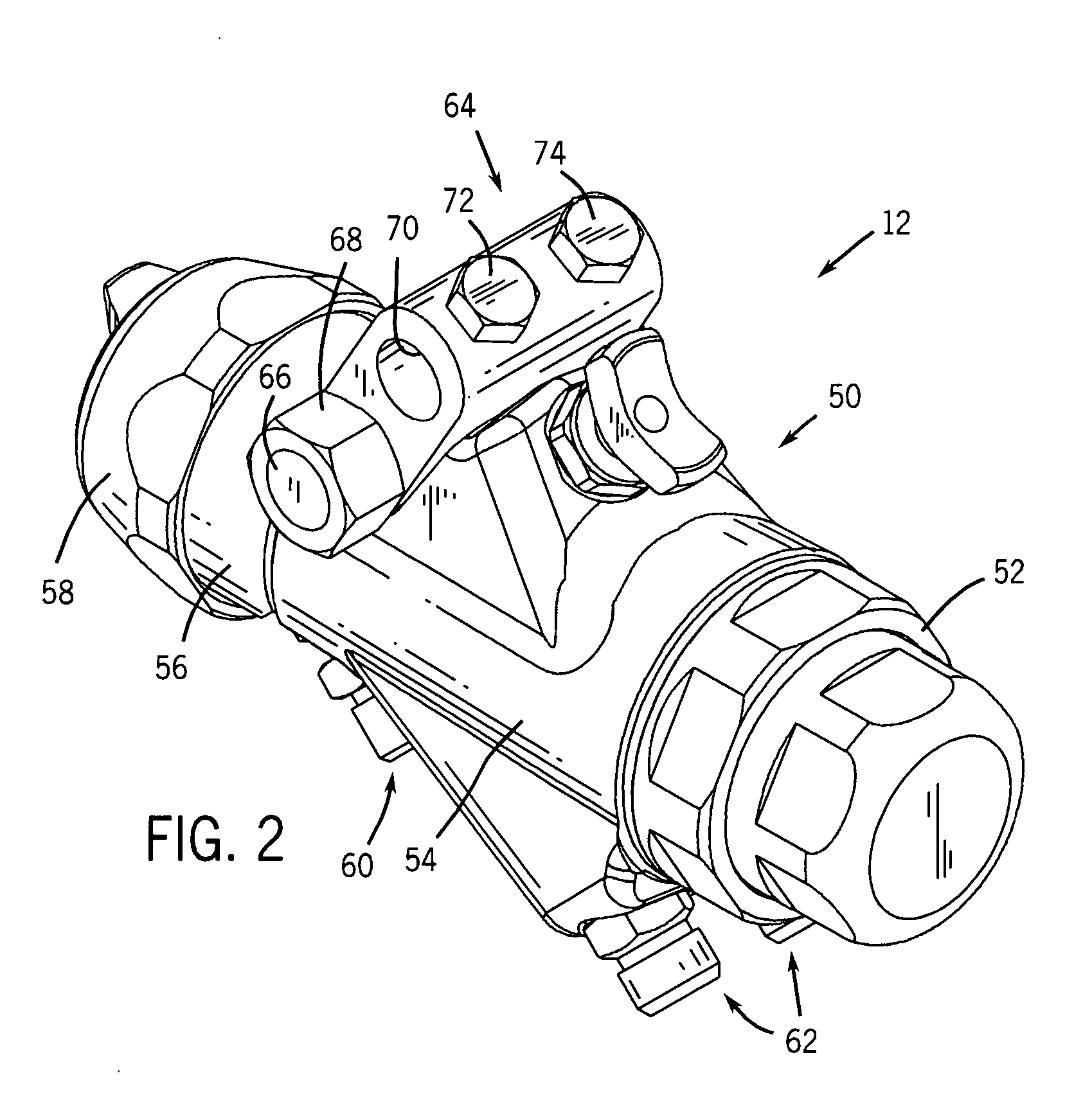
[0015] As discussed in further detail below, the present technique provides a unique spray device having features that facilitate disassembly, servicing, and repeatable mounting in substantially the same spray position. For example, the spray device of the present technique has various structural features that reduce the likelihood of fluid drainage into undesirable areas of the spray device during disassembly and servicing. The present spray device also has a unique mounting mechanism, which preserves the desired mounting position for the spray device in the event of dismounting and subsequent remounting of the spray device.

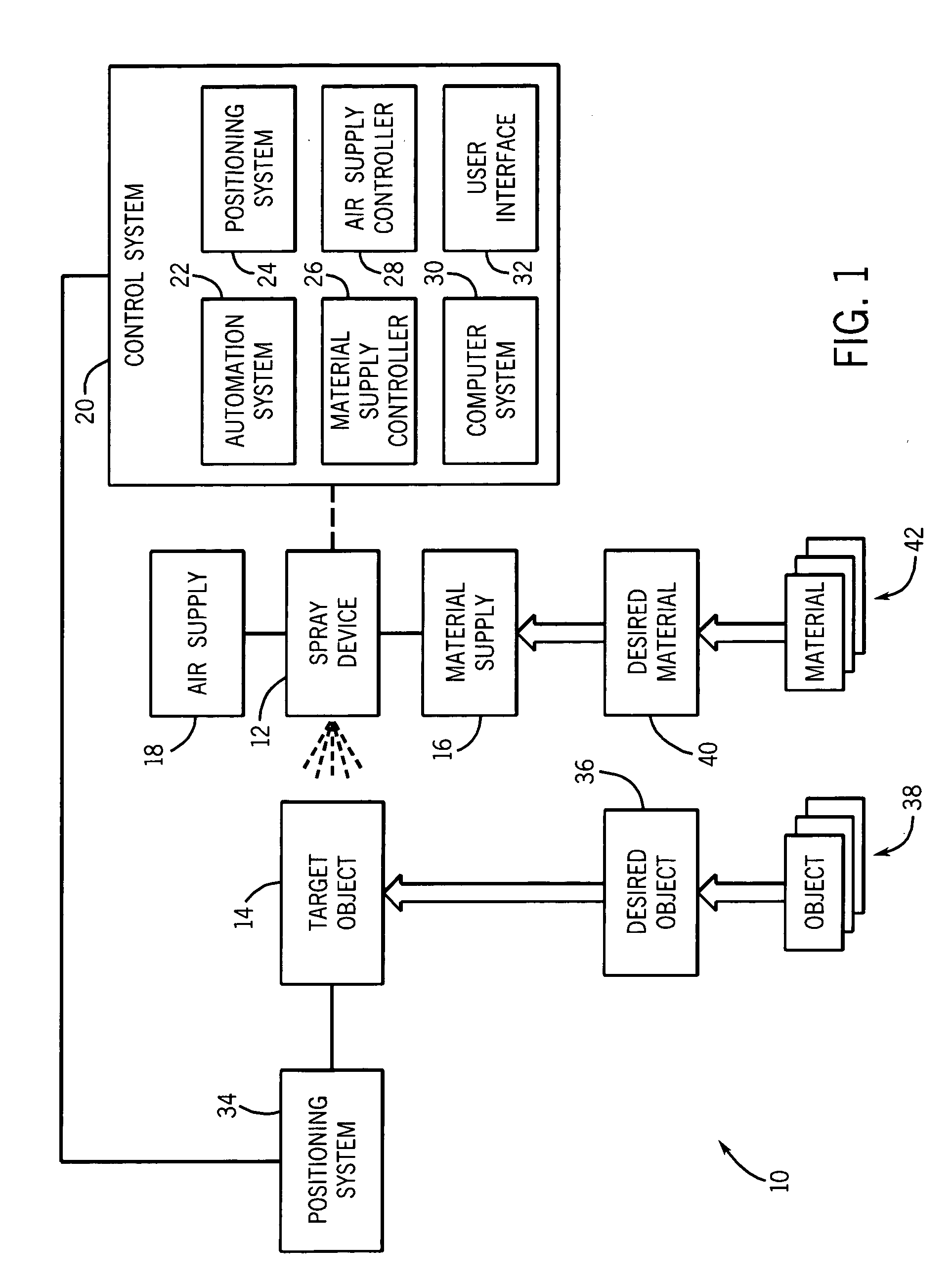
[0016] Turning now to the figures, FIG. 1 is a flow chart illustrating an exemplary spray system 10, which comprises a spray device 12 for applying a desired material to a target object 14. For example, the spray device 12 may comprise an air atomizer, a rotary atomizer, an electrostatic atomizer, or any other suitable spray formation mechanism. The spray devic...