Transmission/distribution line fault indicator with remote polling and current sensing and reporting capability

Inactive Publication Date: 2005-07-14
DONOVAN DAVID L +2
View PDF19 Cites 260 Cited by
  • Summary
  • Abstract
  • Description
  • Claims
  • Application Information

AI Technical Summary

Benefits of technology

[0011] The present invention is directed to fault indicators and systems using the same, where the fault indicators monitor conditions of transmission / distribution lines along an electrical transmission / distribution network. Such fault indicators provide multiple functionality and transmit fault sensing data, as well as other condition data to a remote location for processing. The fault indicators of the present invention may include one-way communication to transmit the condition data to a remote location, or be provided with two-way communication capability to respond to a polling request from a remote location and transmit condition data in response to such a request. In a further detailed exemplary embodiment, the fault indicators include memory devices operatively coupled thereto to log the real-time data in a chronological fashion. Such log data may be transmitted to a remote monitoring station in a data packet at predetermined intervals, or may likewise include a cyclical memory storage that continuously saves over existing, previously logged condition data.

Problems solved by technology

Numerous problems may arise during the transmission / distribution of electric current such as faults and large current usage disparities between network grids.

Method used


Image

  • Transmission/distribution line fault indicator with remote polling and current sensing and reporting capability
  • Transmission/distribution line fault indicator with remote polling and current sensing and reporting capability

Examples


Embodiment Construction

[0013] It should be understood that the following detailed description of exemplary embodiments of the present invention are exemplary in nature and are not intended to constitute limitations upon the present invention. It is also to be understood that variations of exemplary embodiments contemplated by one of ordinary skill in the art shall concurrently fall within the scope and spirit of the invention. Although certain aspects of the exemplary embodiments are shown in more detail, some features within the purview of one skilled in the art may have been omitted for the sake of clarity and brevity.

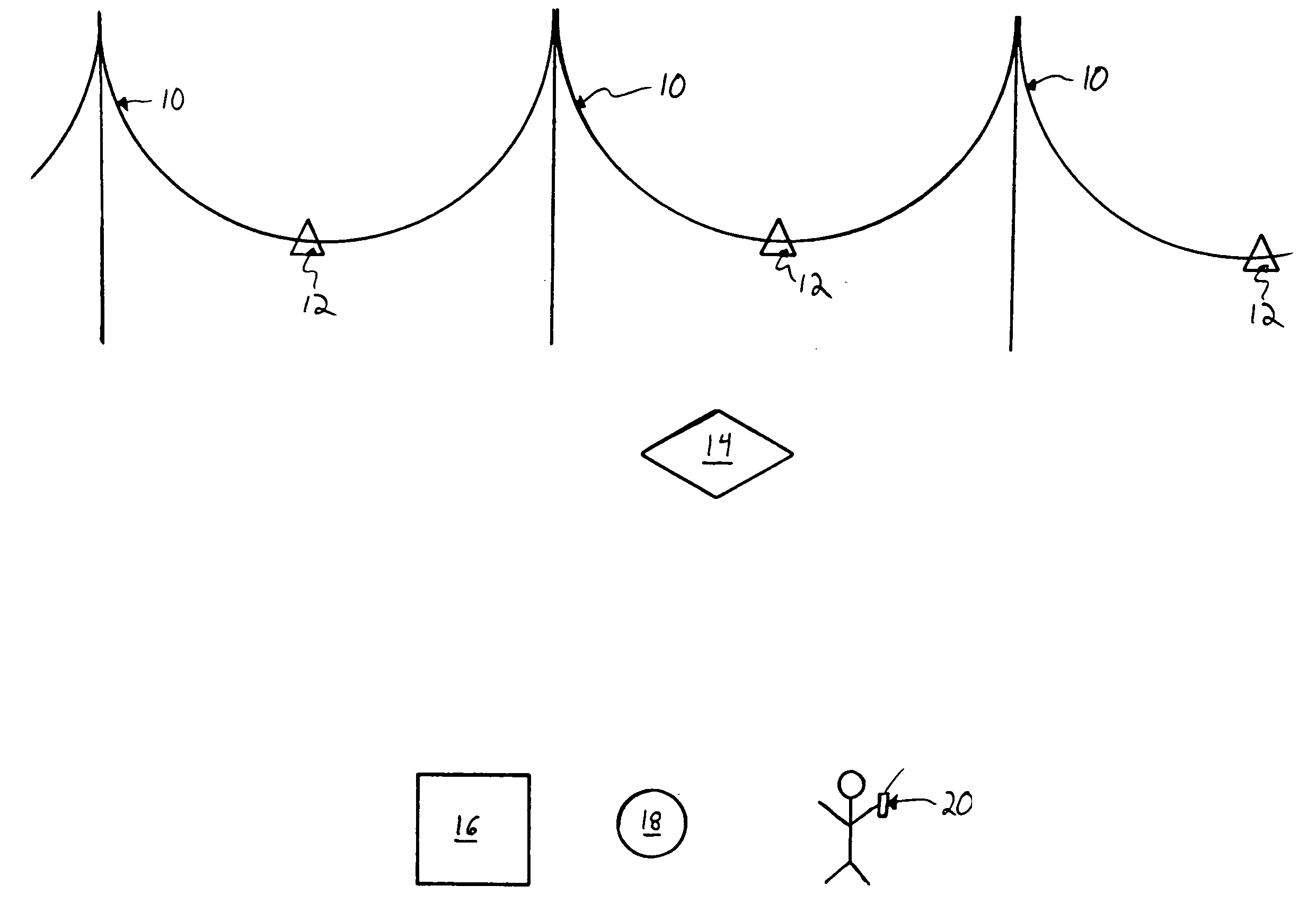
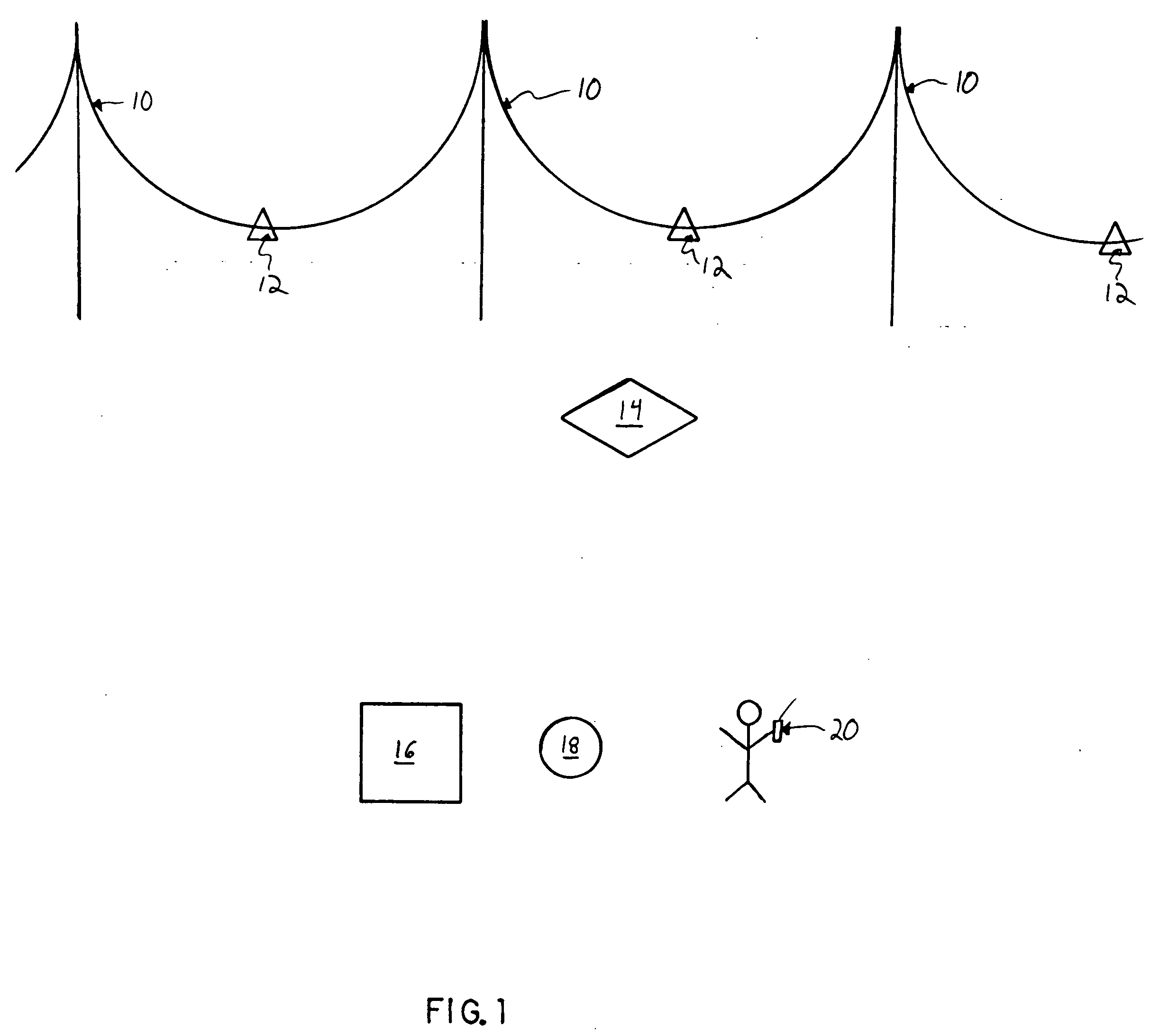
[0014] Referencing FIG. 1, a schematic diagram is provided showing an electrical transmission / distribution line 10 having a plurality of fault indicators 12 in accordance with the present invention. The fault indicators 12 include remote communication capability to transmit condition data to a local receiving center 14, a central monitoring station 16, a mobile monitoring station (such as...


PUM

PropertyMeasurementUnit
currentaaaaaaaaaa
current loadaaaaaaaaaa
electricalaaaaaaaaaa

Abstract

The present invention includes a fault indicator for an electrical transmission line comprising: a fault indicator circuit; and a remote communicator operatively coupled to the fault indicator circuit to transmit condition data to a remote location, where such condition data includes current load data. The invention also includes a method of monitoring and responding to current faults and load variations across an electrical transmission network, the method comprising: installing two fault indicators in electrical communication with an electrical transmission network and including two-way communication capability; generating, by the two fault indicators, condition data specific to a respective location of each of the two fault indicators, where such condition data includes current load data; transmitting the condition data from the two fault indicators to a remote location; receiving, at the remote location, the condition data transmitted from the two fault indicators; and, monitoring and processing the condition data received.

Description

CROSS REFERENCE TO RELATED APPLICATIONS [0001] This application claims the benefit of U.S. Provisional Patent Application Ser. No. 60 / 528,851, filed Dec. 11, 2003, and entitled “TRANSMISSION / DISTRIBUTION LINE FAULT INDICATOR WITH REMOTE POLLING AND CURRENT SENSING AND REPORTING CAPABILITY,” the disclosure of which is incorporated herein by reference.BACKGROUND [0002] 1. Field of the Invention [0003] The present invention is directed to fault indicators and systems using the same, where the fault indicators monitor conditions of transmission / distribution lines along an electrical transmission / distribution network. [0004] 2. Background of the Invention [0005] Electrical transmission / distribution lines convey electric current from generation stations to points of use. Numerous problems may arise during the transmission / distribution of electric current such as faults and large current usage disparities between network grids. Fault indicators were developed, in response to a need, to ide...

Claims


Application Information

Patent Timeline
Patent Type & Authority Applications(United States)
IPC IPC(8): G01LG08B21/00
CPCG01R31/085H02G7/00G08C25/00
Inventor DONOVAN, DAVID L.JOYCE, ROBERT E.SABADOS, LANCE P.
Owner DONOVAN DAVID L
Why Eureka
Try Eureka