Image-forming device

a technology of forming device and forming head, which is applied in the direction of typewriters, power drive mechanisms, printing, etc., can solve the problems of inflexible bending back on itself in a direction orthogonal, wearout and breakage of the twisted portion, broken or disconnected wiring, etc., and achieves the effect of minimizing internal space waste, facilitating maintenance and ink cartridge replacement operations, and compact structur

Active Publication Date: 2005-07-14
BROTHER KOGYO KK
View PDF15 Cites 69 Cited by
  • Summary
  • Abstract
  • Description
  • Claims
  • Application Information

AI Technical Summary

Benefits of technology

[0014] To eliminate twisting of the flexible flat cable, the middle portion of the cable can be bent back at right angles and the cable can be laid out orthogonal to the pivotal axis. However, even in this case, the movement of the image sensor applies a large force to the bent portions of the cable, bending these portions repeatedly and resulting in wire breakage. Hence, this problem has yet to be resolved.
[0017] In the view of foregoing, it is an object of the present invention to overcome the above problems, and also to provide an image-forming device that can be made more compact by minimizing wasted internal space.
[0018] It is another object of the present invention to provide an image-forming device that facilitates maintenance and ink cartridge replacement operations by ensuring that the middle portion of a flexible flat cable does not get in the way of such operations when an upper frame supporting a scanning mechanism is opened fully, while preventing twisting in the middle portion of the cable.

Problems solved by technology

However, in the image-forming device of Japanese unexamined patent application publication No. 2003-298790, in particular, a flexible flat cable with numerous wires is normally used to connect the image sensor and the control board, and this flexible flat cable is flexible enough to bend back on itself in a direction substantially parallel to the longitudinal direction of the wiring, but not flexible enough to bend back on itself in a direction orthogonal to the longitudinal direction of the wiring.
When the image-forming device is used over a long period of time and the scanning unit (upper frame) is repeatedly opened and closed, repeated bending of the flexible flat cable tends to result in wearing out and breakage of the twisted portion (broken or disconnected wiring).
However, even in this case, the movement of the image sensor applies a large force to the bent portions of the cable, bending these portions repeatedly and resulting in wire breakage.
Hence, this problem has yet to be resolved.
Another problem is that, when the media board and the main control board are disposed at separate locations, wiring is needed to connect these two boards.
Further, being a serial head, the inkjet head is configured to move beyond both widthwise edges of the recording sheet, leaving wasted space on both sides of the sheet conveying path.

Method used


Image

  • Image-forming device
  • Image-forming device
  • Image-forming device

Examples


first embodiment

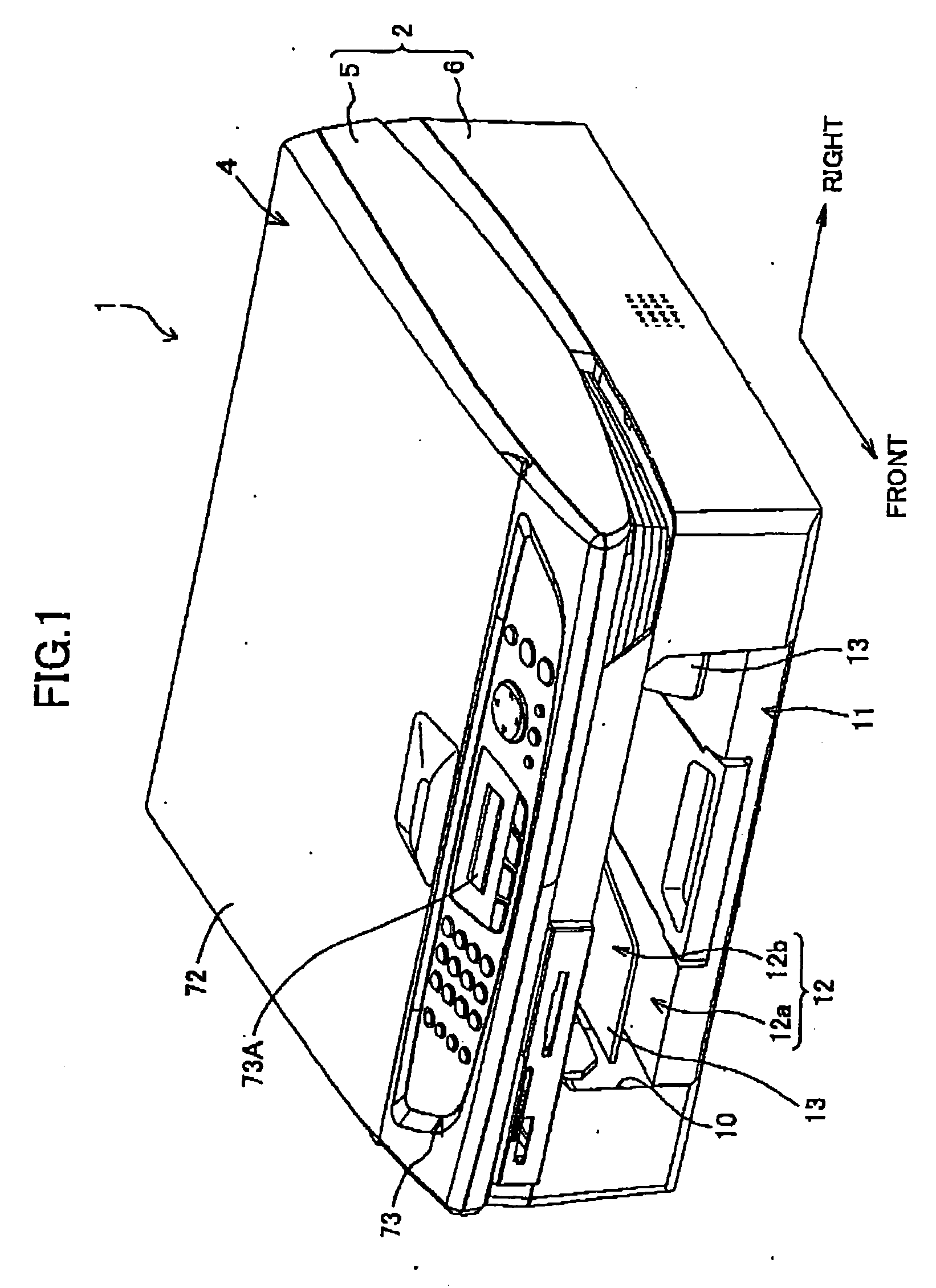
[0052] First, a multifunctional device 1 according to the present invention will be described with reference to FIGS. 1 to 13.

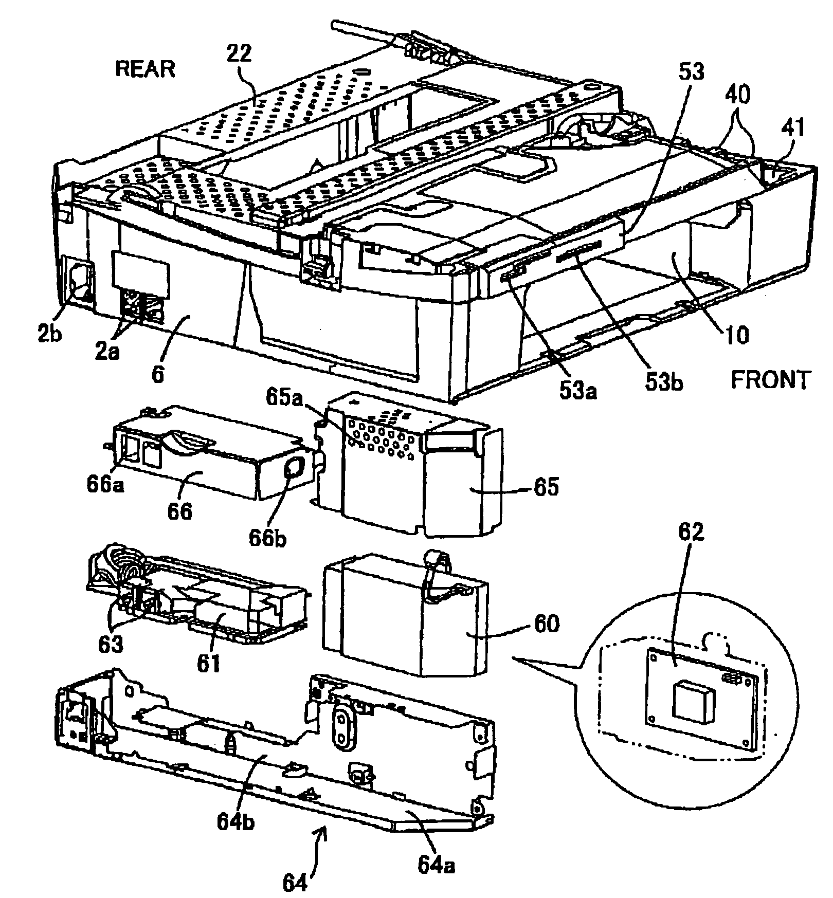
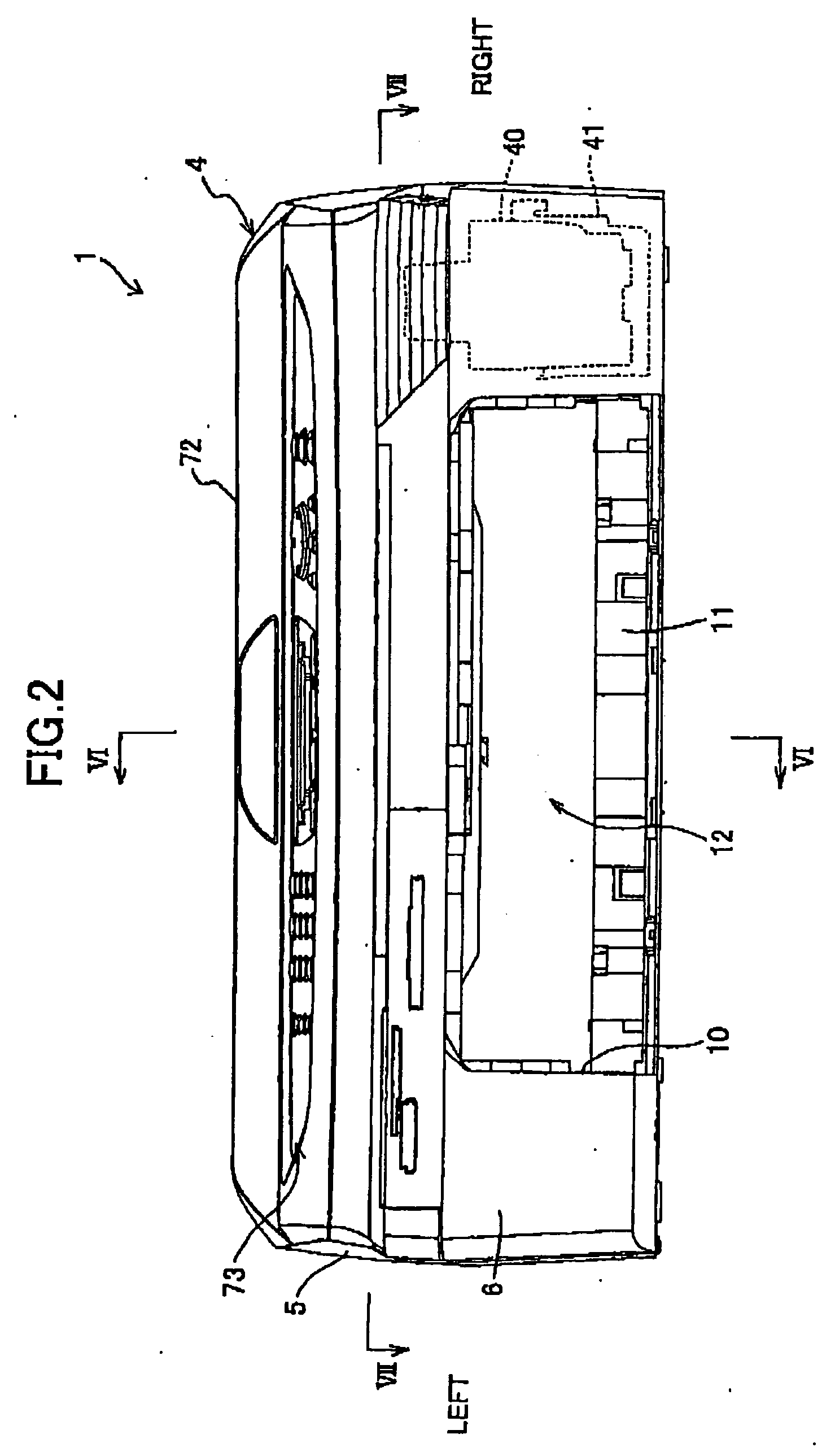
[0053] As shown in FIG. 1, the multifunctional device 1 includes a main casing 2 having an upper frame 5 and a lower frame 6. The lower frame 6 is formed in a substantially square shape in a plan view. A sheet accommodating section 10 is formed as a recess in the front bottom portion of the lower frame 6 and centered left-to-right, providing an arch-like front appearance to the lower frame 6. A conveying space 12 is defined inside the sheet accommodating section 10 for conveying a recording sheet P (see FIG. 12) in the front-to-rear direction.

[0054] A sheet supply tray 11 for holding the recording sheets P is detachably inserted into the sheet accommodating section 10 and is capable of moving in the front-to-rear direction within the conveying space 12. When accommodated in the sheet accommodating section 10, the sheet supply tray 11 blocks the bottom of the...

second embodiment

[0099] Next, a multifunctional device 1B according to the present invention will be described with reference to FIGS. 17 to 21, wherein like parts and components have been given the same reference numerals to avoid duplicating description.

[0100] As shown in FIG. 19, the multifunctional device 12 includes an upper frame 5B and a lower frame 6B. The lower frame 6B is formed in an open-top box shape and includes a front plate 6a, side plates 6b, 6c, and a bottom plate 6d (FIG. 21). The upper frame 5B is pivotably supported by the side plate 6b via the shafts 14. The rear end of the bottom frame 6B is covered with a rear cover 19 shown in FIG. 21.

[0101] As shown in FIG. 17, a sheet supply tray 11B is disposed in the left-to-right center region of the lower frame 6B and accommodates a stack of recording sheets P. The sheet supply tray 11B can be pulled out from the front surface of the lower frame 6B.

[0102] Further, as shown in FIG. 18, disposed inside the lower frame 6B are a conveyin...


PUM


Abstract

A multifunctional device including a lower frame, a main control board, and a cartridge holder. A conveying space is formed in the lower frame farther forward than a recording unit and includes a discharge space for receiving discharged recording sheet. The main control board is disposed horizontally above the conveying space when viewed from the front. The recording unit is disposed farther rearward than the conveying space, with its topmost part substantially equal in height to the main control board. The cartridge holder is disposed to the side of the conveying space and the main control board and fits vertically within the top part.

Description

BACKGROUND OF THE INVENTION [0001] 1. Field of the Invention [0002] The present invention relates to an image-forming device for forming images on a recording medium. [0003] 2. Related Art [0004] There have been proposed multifunctional image-forming devices that include a printer function, a facsimile function, a copier function, and the like. One such image-forming device well known in the art is provided with an inkjet printing unit on its lower frame and a flatbed scanning unit on its upper frame. The flatbed scanning unit has an image-scanning function implemented by a contact image sensor (CIS), a charge-coupled device (CCD), or the like. [0005] For example, an image-forming device disclosed in Japanese unexamined patent application publication No. 2003-298790 includes a main casing (lower frame) formed with a discharge opening in its front side, a printing unit disposed in the main casing and including an inkjet head for ejecting ink onto a recording sheet, a backward-tilting...

Claims


Application Information

Patent Timeline
Patent Type & Authority Applications(United States)
IPC IPC(8): B41J29/02
CPCB41J29/02
Inventor ISHIDA, KAZUHITODESHIMARU, TERUOASADA, TETSUOSAWAKI, YUKICHIOHAMA, TAKASHI
Owner BROTHER KOGYO KK
Why Eureka
Try Eureka