Image conversion device and image conversion method

a technology of image conversion and image, which is applied in the direction of signal generators with optical-mechanical scanning, television systems, color signal processing circuits, etc., can solve the problems large noise of large difference in luminance value, and inability to accurately judge pictures, etc., to achieve accurate and precise motion amount and high resolution

Inactive Publication Date: 2005-07-14
PANASONIC CORP
View PDF10 Cites 12 Cited by
  • Summary
  • Abstract
  • Description
  • Claims
  • Application Information

AI Technical Summary

Benefits of technology

[0079] In this case, the motion amount is calculated on the basis of the first progressive signal and the second progressive signal, so that a more accurate and precise motion amount can be calculated. Even when a picture having a large luminance value i

Problems solved by technology

In the method as in the conventional example, however, when a picture having a large luminance difference in the vertical direction moves slowly, accurate judgment cannot be made.
Therefore, inter-frame interpolation processing suitable for the still picture and intra-field interpolation processing suitable for t

Method used


Image

  • Image conversion device and image conversion method
  • Image conversion device and image conversion method
  • Image conversion device and image conversion method

Examples


first embodiment

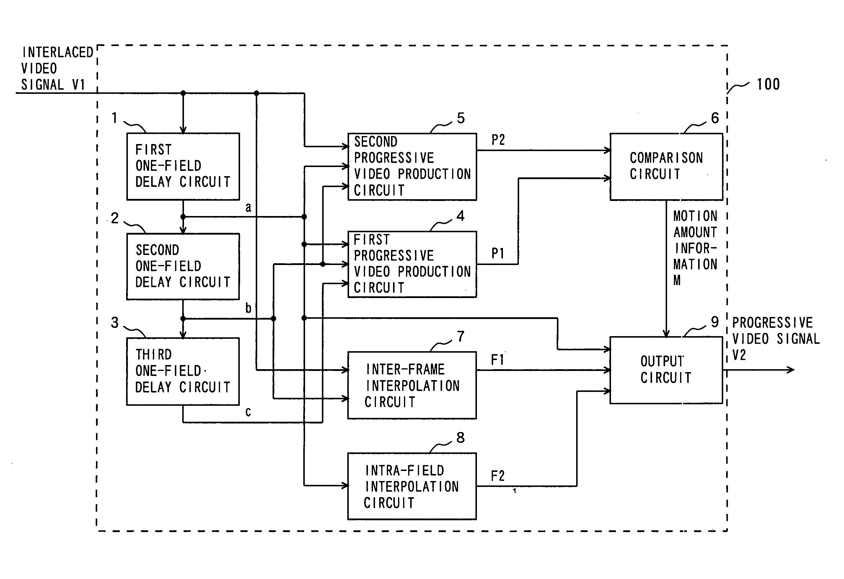
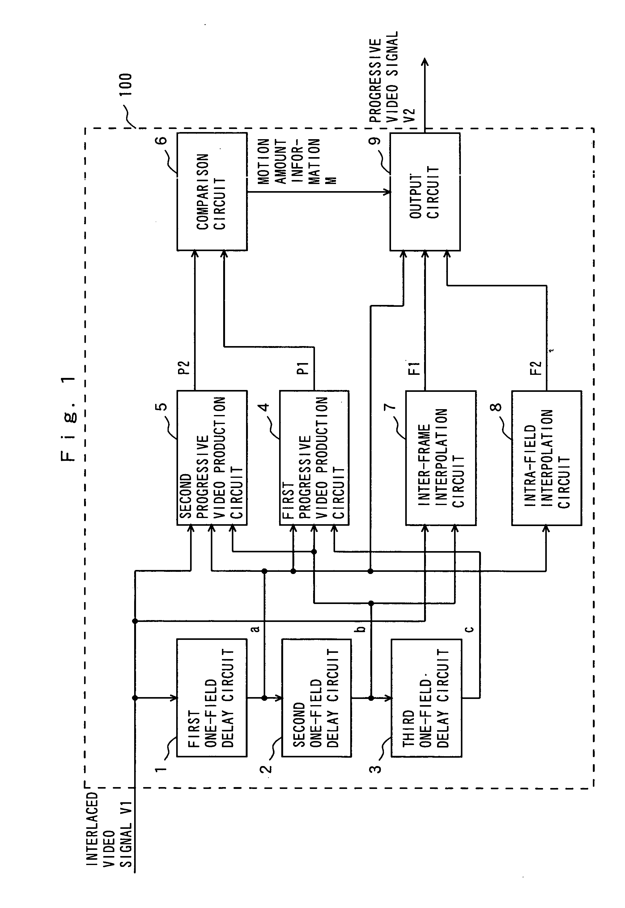
[0099]FIG. 1 is a block diagram showing a picture conversion apparatus 100 according to a first embodiment of the present invention. The picture conversion apparatus 100 shown in FIG. 1 comprises a first one-field delay circuit 1, a second one-field delay circuit 2, a third one-field delay circuit 3, a first progressive video generation circuit 4, a second progressive video generation circuit 5, a comparison circuit 6, an inter-frame interpolation circuit 7, an intra-field interpolation circuit 8, and an output circuit 9. Further, the picture conversion apparatus 100 comprises a timing generation circuit (not shown) for generating a timing signal required for each block upon receipt of a signal which is synchronized with an interlaced video signal V1 and a signal corresponding thereto.

[0100] The operations of the picture conversion apparatus 100 will be described below. First, the interlaced video signal V1 is successively delayed by the first one-field delay circuit 1, the second ...

second embodiment

[0198] A picture conversion apparatus according to a second embodiment will be described. In the picture conversion apparatus according to the second embodiment, a plurality of virtual pixels are newly generated between lines in the progressive video field signal P1 and the progressive video field signal P2 which are respectively generated by the first progressive video generation circuit 4 and the second progressive video generation circuit 5 shown in FIG. 1.

[0199] As a result, the picture conversion apparatus according to the second embodiment can detect motion information more precisely on the basis of the plurality of virtual pixels even when a picture slowly moves at a rate of not more than one line per field, as compared with the picture conversion apparatus 100 according to the first embodiment, as well as to realize optimum control of still picture processing and moving picture processing.

[0200]FIG. 7 is a block diagram showing the picture conversion apparatus according to...

third embodiment

[0292] A picture conversion apparatus 100b according to a third embodiment of the present invention will be described. FIG. 11 is a block diagram showing the configuration of the picture conversion apparatus 100b according to the third embodiment.

[0293] The picture conversion apparatus 100b shown in FIG. 11b is the same as the picture conversion apparatus 100 according to the first embodiment shown in FIG. 1 except that the frame interfield interpolation circuit 7 is eliminated, a non-adaptive region detection circuit 12 is added, and an output circuit 9b is included in place of the output circuit 9 and hence, the same constituent elements are assigned to the same reference numerals, and only different constituent elements will be described.

[0294] An interlaced video signal V1 and an interlaced video signal a which is an output signal from a first one-field delay circuit 1 are fed to the non-adaptive region detection circuit 12 shown in FIG. 11.

[0295] The non-adaptive region dete...


PUM


Abstract

A plurality of interlaced video signals respectively corresponding to a plurality of continuous fields are generated by first, second, and third one-field delay circuits on the basis of an inputted interlaced video signal. A first progressive video field signal is generated by a first progressive video generation circuit on the basis of the plurality of interlaced video signals. A second progressive video field signal is generated by a second progressive video generation circuit on the basis of the plurality of interlaced video signals. Motion amount information in the vertical direction of a picture is calculated by a comparison circuit on the basis of the first progressive video field signal and the second progressive video field signal.

Description

TECHNICAL FIELD [0001] The present invention relates to a picture conversion apparatus and a picture conversion method for converting an interlaced video signal into a progressive video signal. BACKGROUND ART [0002] In order to convert interlaced video signals into progressive video signals, motion adaptive progressive conversion apparatuses have been conventionally employed. [0003]FIG. 14 illustrates an example of an interlaced video signal. An interlaced video signal in one frame is transmitted as a picture in two fields. For example, when L is an even value, signals on even-numbered lines such as the L-th line, the (L+2)-th line, the (L+4)-th line, the (L+6)-th line, and the (L+8)-th line are transmitted in the N-th field. Subsequently, signals on odd-numbered lines such as the (L+1)-th line, the (L+3)-th line, the (L+5)-th line, and the (L+7)-th line are transmitted in the (N+1)-th field. Further, signals on the same even-numbered lines as those in the N-th field are transmitted...

Claims


Application Information

Patent Timeline
IPC IPC(8): H04N7/01H04N5/14
CPCH04N5/144H04N7/0137H04N7/012H04N7/01
Inventor KASAHARA, MITSUHIRODAIGI, TOMOAKIKAWAMURA, HIDEAKINAKAHIGASHI, HIDETOMORITA, TOMOKO
Owner PANASONIC CORP
Why Eureka
Try Eureka