Bracing apparatus

a technology of bracketing and upper casing, which is applied in the direction of machine supports, electric apparatus casings/cabinets/drawers, instruments, etc., can solve the problems of unsatisfactory large problem of users allocating space to accommodate those machines in a limited office environment, etc., to avoid the upper casing from hurting the hands of users, improve the convenience of replacement operation, and prevent the effect of the upper casing

Inactive Publication Date: 2005-07-14
LITE ON TECH CORP
View PDF4 Cites 1 Cited by
  • Summary
  • Abstract
  • Description
  • Claims
  • Application Information

AI Technical Summary

Benefits of technology

[0006] The primary object of the invention is to provide a bracing apparatus adopted for use on hatch-top electronic devices, that provides a sufficient force to support the upper casing of the electronic devices in a steady manner, when electronic elements in the lower casing of the electronic devices are being replaced. Thereby, the invention improves replacement convenience and prevents the upper casing from incidental closing during replacement operations, to avoid hurting user's hands.

Problems solved by technology

However, because the machines are designed and made by different vendors, their operation is also different.
As each machine requires a space for installation, allocating space to accommodate those machines in a limited office environment is a big problem for users.
It is obvious that convenience for the replacement operation set forth above is not desirable.

Method used


Image

  • Bracing apparatus
  • Bracing apparatus
  • Bracing apparatus

Examples


Embodiment Construction

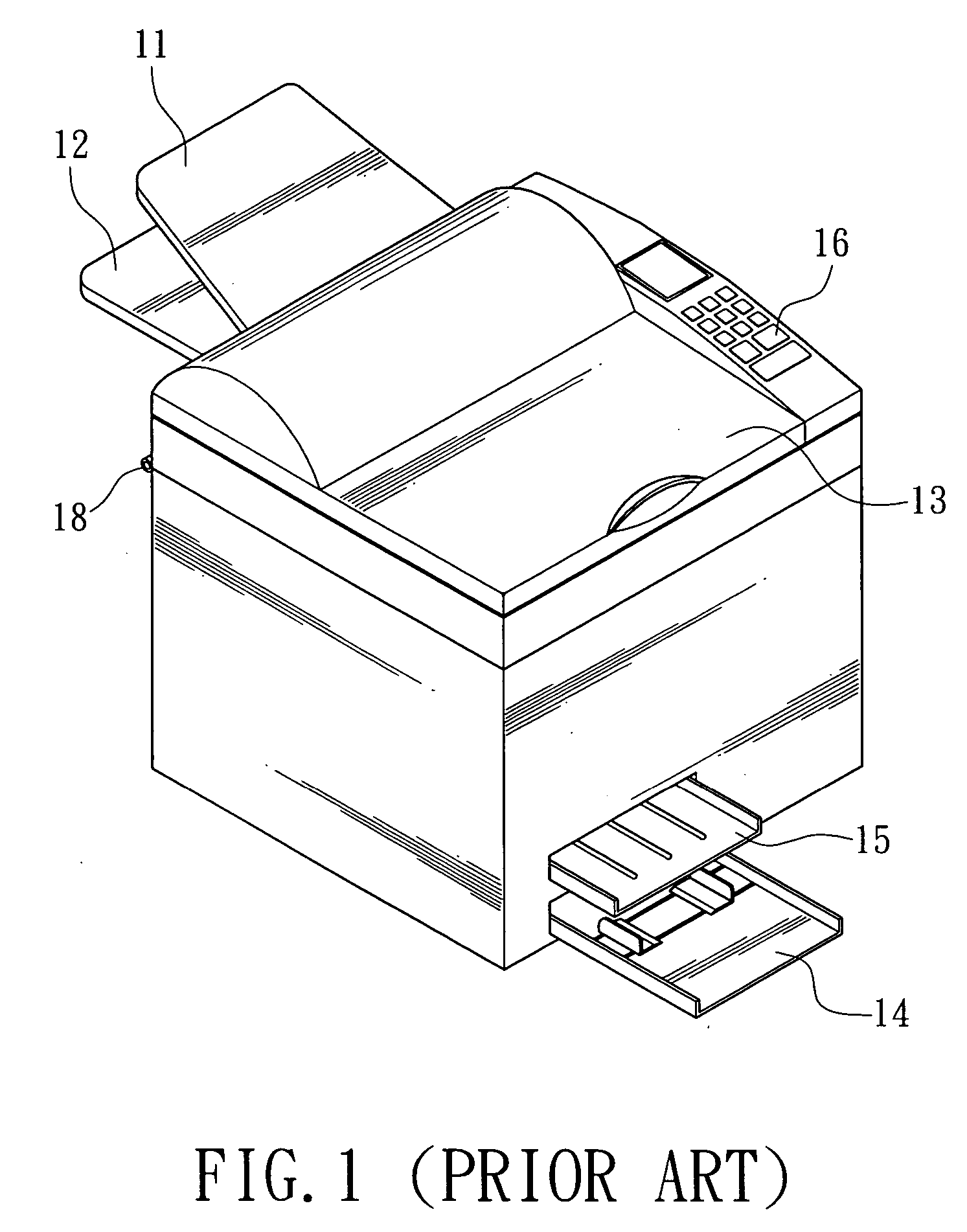
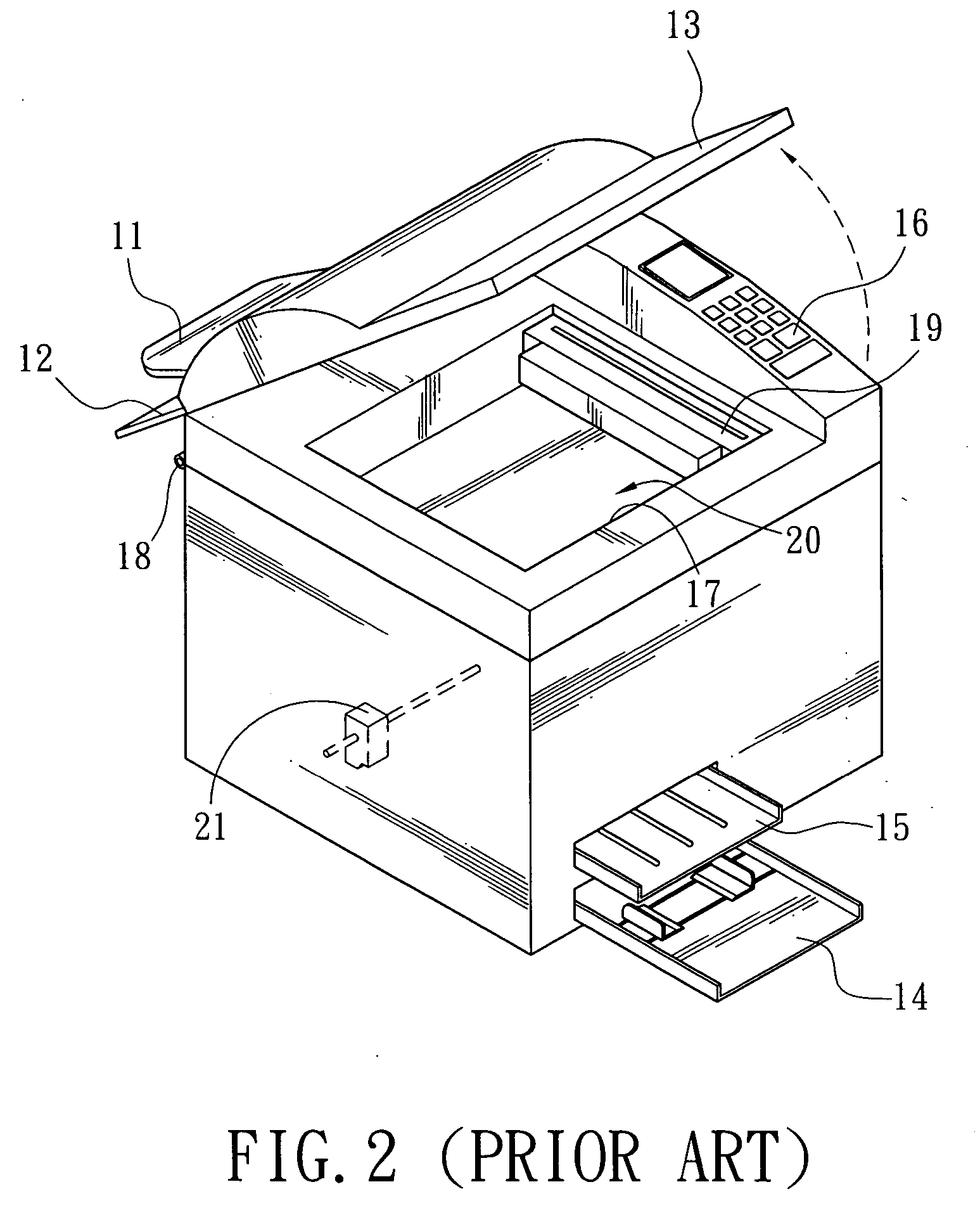
[0019] Referring to FIG. 5, the bracing apparatus of the invention is adopted for use on hatch-top electronic devices. A MFP 4 is used as an example for the description below. The MFP 4 includes an upper casing 41 and a lower casing 42 that are pivotally engaged with each other and contain electronic elements therein. Hence after the upper casing 41 is pivotally turned relative to the lower casing 42, the invention can support the upper casing 41 and prevent the upper casing from incidental closing and avoid hurting user's hands.

[0020] The bracing apparatus of the invention includes first linkage bars 51, second linkage bars 52 and elastic elements 53. Each first linkage bar 51 has a first connection end 511 connecting to the upper casing 41, remote from the pivotal joint of the upper casing 41 and the lower casing 42. The second linkage bar 52 has a second connection end 521, connecting to the lower casing 42, at a location corresponding to where the first linkage bar 51 connects ...


PUM


Abstract

A bracing apparatus adopted for bracing an upper casing, pivotally engaged with a lower casing with electronic elements inside, of hatch-top electronic devices facilitate repairs and maintenance of the electronic elements in the lower casing. The bracing apparatus includes a first and a second linkage bar and an elastic element. The first linkage bar is remote from the pivotal joint of the upper and the lower casing, connects to the upper casing and pivotally connects to the second linkage bar. The second linkage bar connects to the lower casing. The pivotal connection end of the first and the second linkage bars is directing outwards from the neighboring sides of the upper casing and the lower casing. The elastic element connects to the upper casing abutting the pivotal joint of the upper casing and the lower casing, and the pivotal connection end of the first and the second linkage bars.

Description

FIELD OF THE INVENTION [0001] The invention relates to a bracing apparatus adopted for use on hatch-top electronic devices. BACKGROUND OF THE INVENTION [0002] Nowadays business machines (such as copiers, facsimile machines, printers, scanners, and the like) have become indispensable information equipment in office environments. They not only can enhance working quality and efficiency, but also make storing and management of files and records more convenient and tidy. However, because the machines are designed and made by different vendors, their operation is also different. As each machine requires a space for installation, allocating space to accommodate those machines in a limited office environment is a big problem for users. With the advance of technologies and increasing user demands, integrating multiple functions has become a prevailing direction in the design of information products these days. The goal is to integrate multiple functions in a single multi-function peripheral...

Claims


Application Information

Patent Timeline
Patent Type & Authority Applications(United States)
IPC IPC(8): B41J29/02G06F1/16
CPCB41J29/02
Inventor CHAO, MIN
Owner LITE ON TECH CORP
Why Eureka
Try Eureka