Image forming apparatus

Active Publication Date: 2005-07-14
BROTHER KOGYO KK
View PDF12 Cites 24 Cited by
  • Summary
  • Abstract
  • Description
  • Claims
  • Application Information

AI Technical Summary

Benefits of technology

[0083] The present invention further provides a computer program for controlling an image forming apparatus which reciprocatingly moves a carriage substantially perpendicular to a feeding direction of a sheet and performs printing to the sheet with a recording head mounted on the carriage. The computer program including: a reciprocating movement program for accelerating the carriage in one direction into a constant speed state, decelerating the carriage after the constant speed state of a short time, and decelerating the carriage after accelerating it in the opposite direction into the constant speed state again, so that the carriage can repeatedly reciprocates. A first determination program determines that the carriage is stopped when decelerated to a speed equal to or lower than a first speed, if the carriage moved based upon the reciprocating movement program is stopped at a predetermined position. A second determination program determines that the carriage is stopped when decelerated to a speed equal to or lower than a second speed higher than the first speed if the carriage is reciprocatingly moved based upon the reciprocating movement program to perform printing.
[0084] According to such a computer program, by operating a CPU based on the computer program, criteria for determination on stop of the carriage reciprocatingly moving at the print time can be varied according to an operation state. When printing is performed, time required for the entire reciprocating movement is reduced by partially making the determination on stop of the carriage earlier. And high-speed printing can be performed easily.
[0085] The present invention further provides a computer program for controlling an image forming apparatus which reciprocatingly moves a carriage substantially perpendicular to a feeding direction of a sheet to perform printing to the sheet with a recording head mounted on the carriage. When the carriage is reversed for reciprocating movement, the apparatus performs feeding of the sheet. The computer program including: a reciprocating movement program for accelerating the carriage in one direction into a constant speed state, decelerating the carriage after the constant speed state of a short time, and decelerating the carriage after accelerating it in the opposite direction into the constant speed state again, thereby repeatedly reciprocating the carriage. When discharge of a sheet is performed, the apparatus retracts the carriage to the outside of a reciprocating movement portion of the carriage. And a carriage movement control program brings the carriage into the constant speed state based upon the recip

Problems solved by technology

However, in order to select and input a sheet type to be used with the input unit of the computer or the like to adjust a gap to a predetermined amount as described above, a complicated electric mechanism member is required.
In addition, in the image forming apparatus in which the lever is operated manually, unless a user knows that the lever is manually operated, the user cannot perform gap adjustment and an image is formed with an inappropriate gap with respect to a thickness of a sheet, which provides inconveniences such as a waste of sheets and a waste of time.
Therefore, there is a problem in that a pressing force of the pressing lever does not act on the positioning of the nozzle portion at all and the recor

Method used


Image

  • Image forming apparatus
  • Image forming apparatus
  • Image forming apparatus

Examples


Example

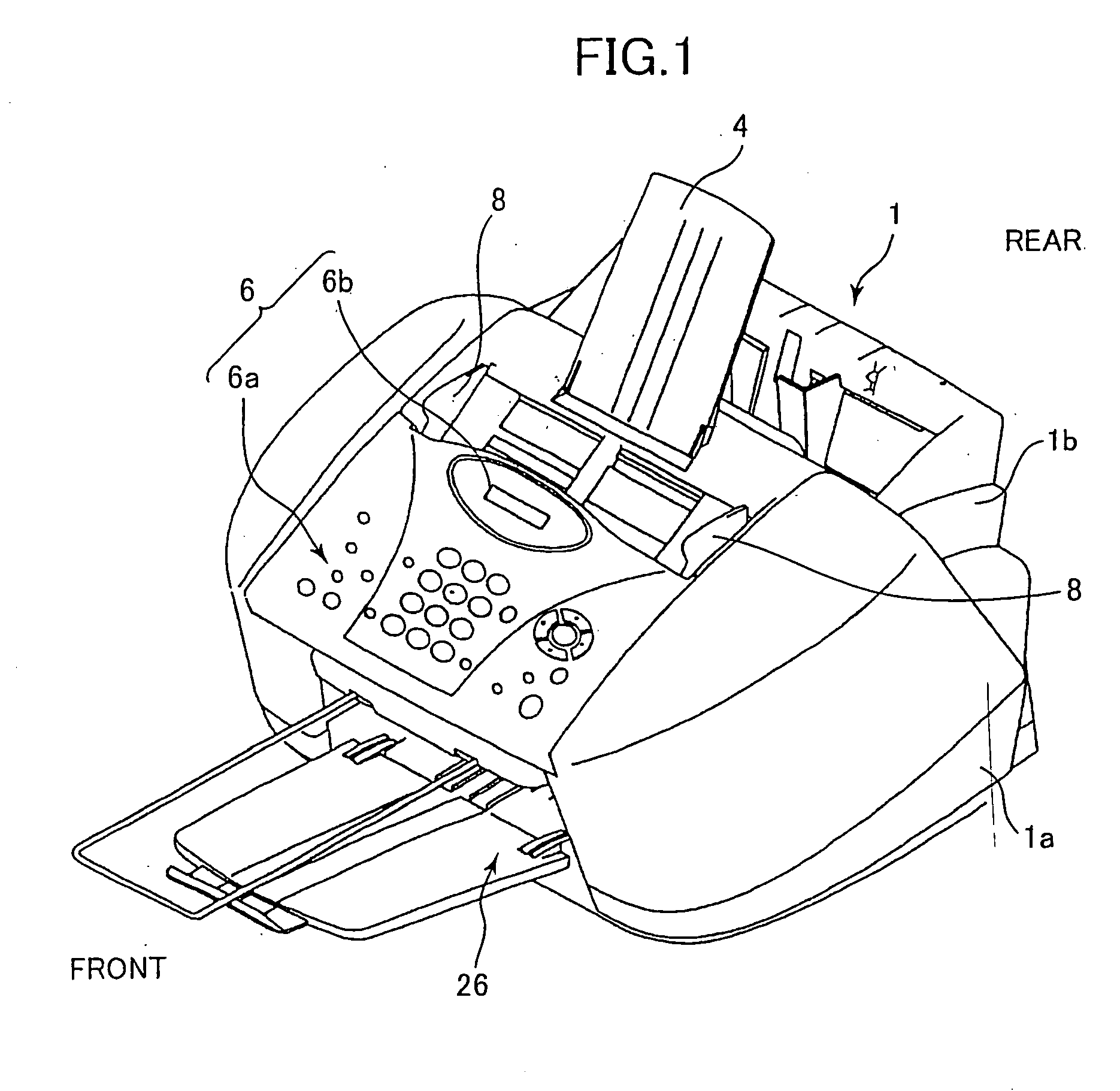
[0159] Next, an image forming apparatus according to a first embodiment of the present invention will be described based upon FIGS. 1 to 26. This image forming apparatus is a multifunction facsimile / printer apparatus.

Outline of the Multifunction Facsimile / Printer Apparatus

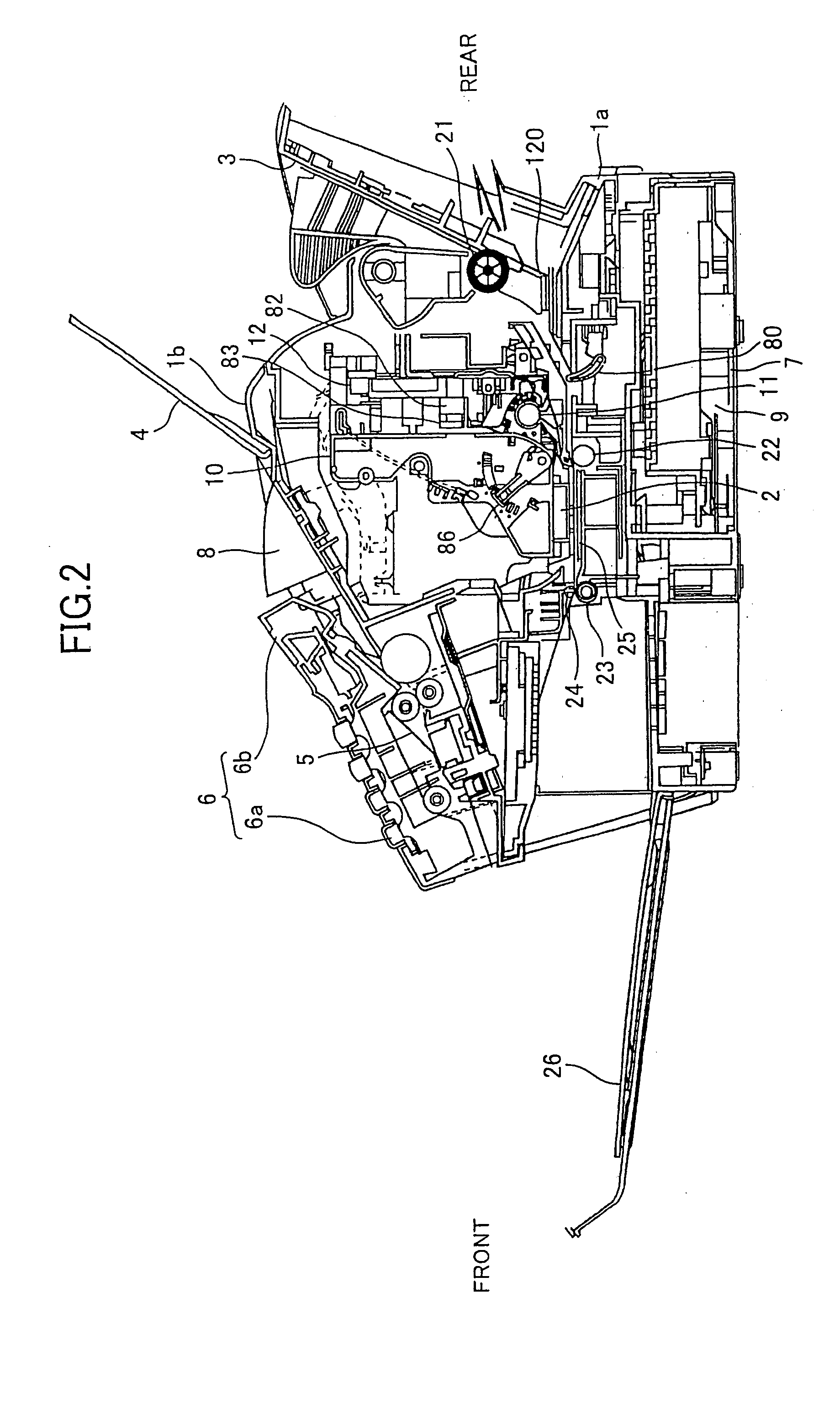
[0160] As shown in FIG. 1, in the multifunction facsimile / printer apparatus, a main body case 1 is constituted by a main lower case 1a made of synthetic resin and an upper case 1b made of synthetic resin covering an upper side of the main lower case 1a. The main lower case 1a receives an ink jet recording portion 2 (FIG. 2) and is provided with a sheet supply tray 3 (FIG. 2) for supplying a sheet P on which an image is formed. The tray 3 is inclined and positioned at a rear upper side of the main lower case 1a. An original mounting portion 4 is positioned in a part close to the rear of the upper case 1b. In that part, a pair of left and right original guide plates 8 are mounted which laterally slides in accordanc...

Example

Second Embodiment Concerning the Gap Adjustment Mechanism

[0235] The gap dimension G1 is switched to two types, a small one and a large one in the above-mentioned first embodiment, switching to three types if gaps can be executed in a gap adjustment mechanism 30a according to this embodiment. As shown in FIGS. 27A and 27B, three states with different heights of abutment portions 59a, 59b, and 59c provided on the surface of the switching block member 13 laterally pivotable are set. Next, the lowest first abutment portion 59a and the second highest second abutment portion 59b are connected by a first inclined guide surface 60a. The highest third abutment portion 59c is set so as to have a second inclined guide surface 60b which is in a position parallel with the second highest abutment portion 59b. Two pushing pieces 61a and 61b of a chevron shape with different heights are provided to be apart from each other appropriately in a moving direction of a carriage on an upper surface of th...

Example

Third Embodiment Concerning the Gap Adjustment Mechanism

[0237] In the gap adjustment mechanisms 30 and 30a according to the first and second embodiments, the abutment portions with different heights of the switching block member 13 are switched to perform size adjustment of the gap by utilizing the first pushing piece 56 and the second pushing piece 57 provided in the frame 12, respectively, according to the reciprocating lateral movement of the carriage 10. The third embodiment relates to a gap adjustment mechanism which is capable of increasing accuracy of gap formation while further miniaturizing and simplifying a structure for adjustment of the gap.

[0238] An upper perspective view of a carriage 10b in accordance with this embodiment is shown in FIG. 28. Since a structure of the carriage 10b is substantially the same as that of the carriage 10 of the first embodiment except the gap adjustment mechanism 30 of the first embodiment, detailed descriptions of the structure will be o...


PUM


Abstract

At a predetermined position during the lateral movement of a carriage 10, a gap switching mechanism 30 for switching a gap between a recording head 15 and a recording medium is provided. The recording head 15 is mounted facing downward on the carriage 10. A part close to one side on a lower end of the carriage is slidably and pivotably supported by a guide shaft 11 of a round shaft shape. A switching block member 13 provided with several abutment portions 52 and 53 with different heights, which are positioned so as to be opposed to a slide portion 12a at an upper end of a frame 12 extending in a vertical direction along a back of the carriage. The A switching block member 13 is pivotably supported by the carriage. A first pushing portion 56 is located at a left end of the frame so as to abut against the switching block member 13. A pivotal posture of the first pushing portion is changed due to the abutment to bring the abutment portion 53 into a slide contact relationship with the frame 12, so that a small gap is provided. A second pushing portion 57 is located at a right end of the frame so as to abut against the switching block member 13, a pivotal posture of the first pushing portion is changed according to the abutment to bring the abutment portion 52 into a slide contact relationship with the frame 12, so that a large gap is provided.

Description

TECHNICAL FIELD [0001] The present invention relates to an image forming apparatus such as a printer, a facsimile apparatus, a copying machine, or a multifunction machine having all functions of the above apparatuses. More particularly, the present invention relates to an image forming apparatus which can adjust a gap between a face of a recording head and a sheet according to a thickness of the sheet, and can mount a recording head unit on a carriage with ease and accuracy. The present invention also relates to a computer program for controlling a print operation of the image forming apparatus. BACKGROUND ART [0002] Up to now, in some of image forming apparatuses such as a facsimile apparatus and a copying machine, a dot-like image is formed on a sheet by placing an ink ribbon on a surface of the sheet and striking the ink ribbon with dot pins of a recording head, or an image is formed on a sheet by discharging ink drops to the sheet from a nozzle of an ink jet head as in an ink je...

Claims


Application Information

Patent Timeline
IPC IPC(8): B41J25/308
CPCB41J25/3086B41J25/308
Inventor UEDA, KIYOSHISHIOHARA, YUKIOYAZAWA, HIROAKISAMOTO, KENJIMURAI, SHUNJIYAMADA, MASATOSHI
Owner BROTHER KOGYO KK
Why Eureka
Try Eureka