
Device and method for trimming samples

a technology for trimming samples and devices, applied in automatic control devices, feeding apparatuses, maintenance and safety accessories, etc., can solve the problems of not being able to use an external trimming device at room temperature, taking up to an hour to produce thin sections, and the method just described according to the existing art can take up to an hour, etc., to achieve the effect of quick production and little oversigh

Active Publication Date: 2005-07-14
LEICA MICROSYSTEMS GMBH
View PDF11 Cites 14 Cited by
  • Summary
  • Abstract
  • Description
  • Claims
  • Application Information

AI Technical Summary

Benefits of technology

[0007] It is therefore the object of the present invention to create a device with which thin sections of a sample can be produced quickly at low temperatures. The intention is also for the trimming operation to proceed quickly and with as little oversight as possible by the user.
[0009] A further object of the invention is to create a method with which thin sections of a sample can be produced quickly at low temperatures. The intention is also for the trimming operation to proceed quickly and with as little oversight as possible by the user.
[0017] The invention has the advantage that a first motor is provided that moves the knife holder in the X direction, and a second motor is provided that moves the knife holder in the Y direction; that the device has associated with it a control unit that controls the motion of the knife holder in the X direction and the motion of the knife holder in the Y direction; and that the first and the second motor are equipped with a measurement means that measures the position of the knife holder in the X direction and Y direction.

Problems solved by technology

If sectioning is performed at low temperature in a cooling chamber, however, it is not possible to use an external trimming device at room temperature.
The method just described according to the existing art can take up to an hour, and therefore usually takes longer than the actual production of thin sections.
The user must set the individual steps on the unit, and is thus “tied” to the unit for sample trimming and cannot perform any other work.

Method used


Image

  • Device and method for trimming samples
  • Device and method for trimming samples
  • Device and method for trimming samples

Examples


Embodiment Construction

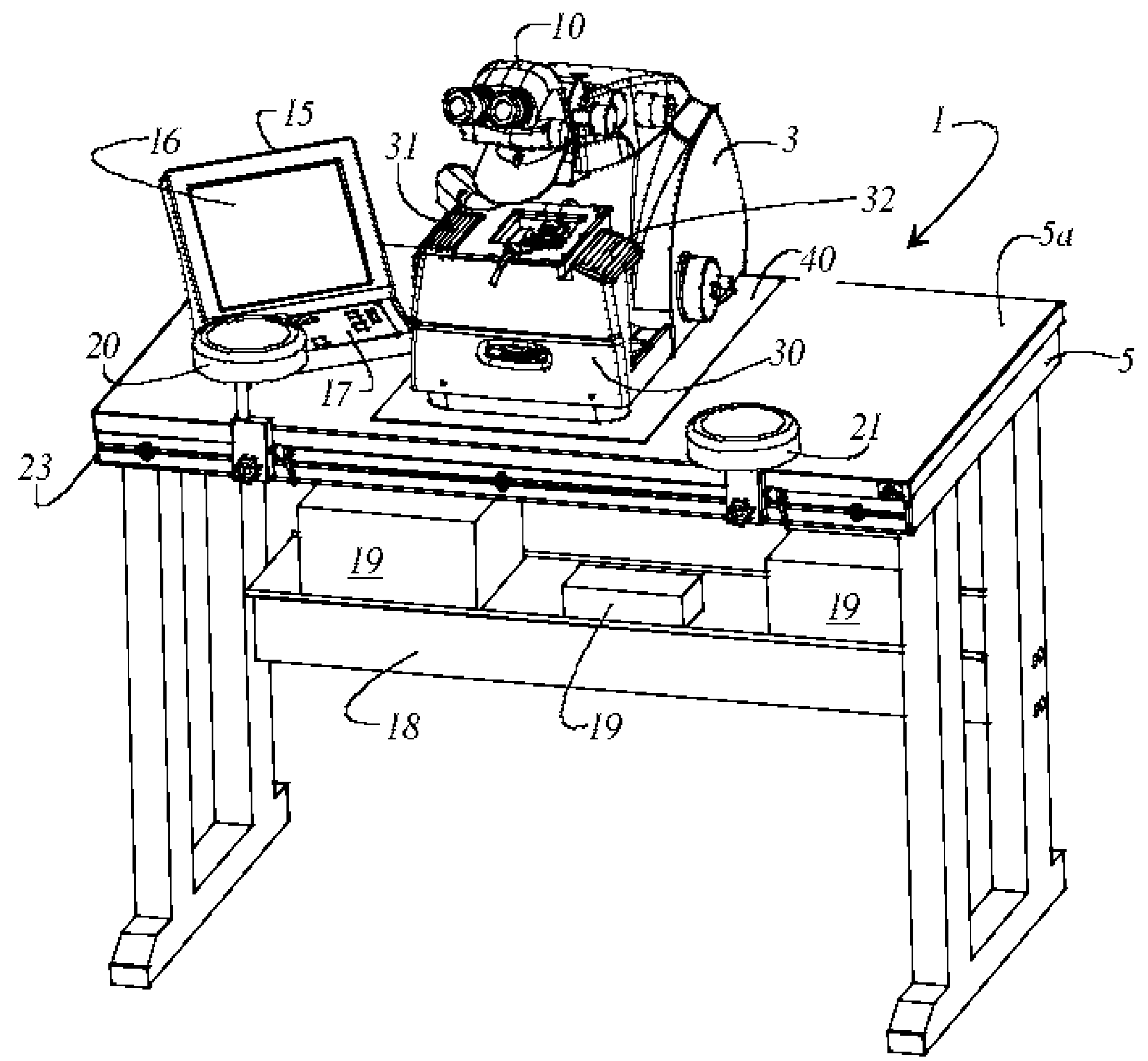
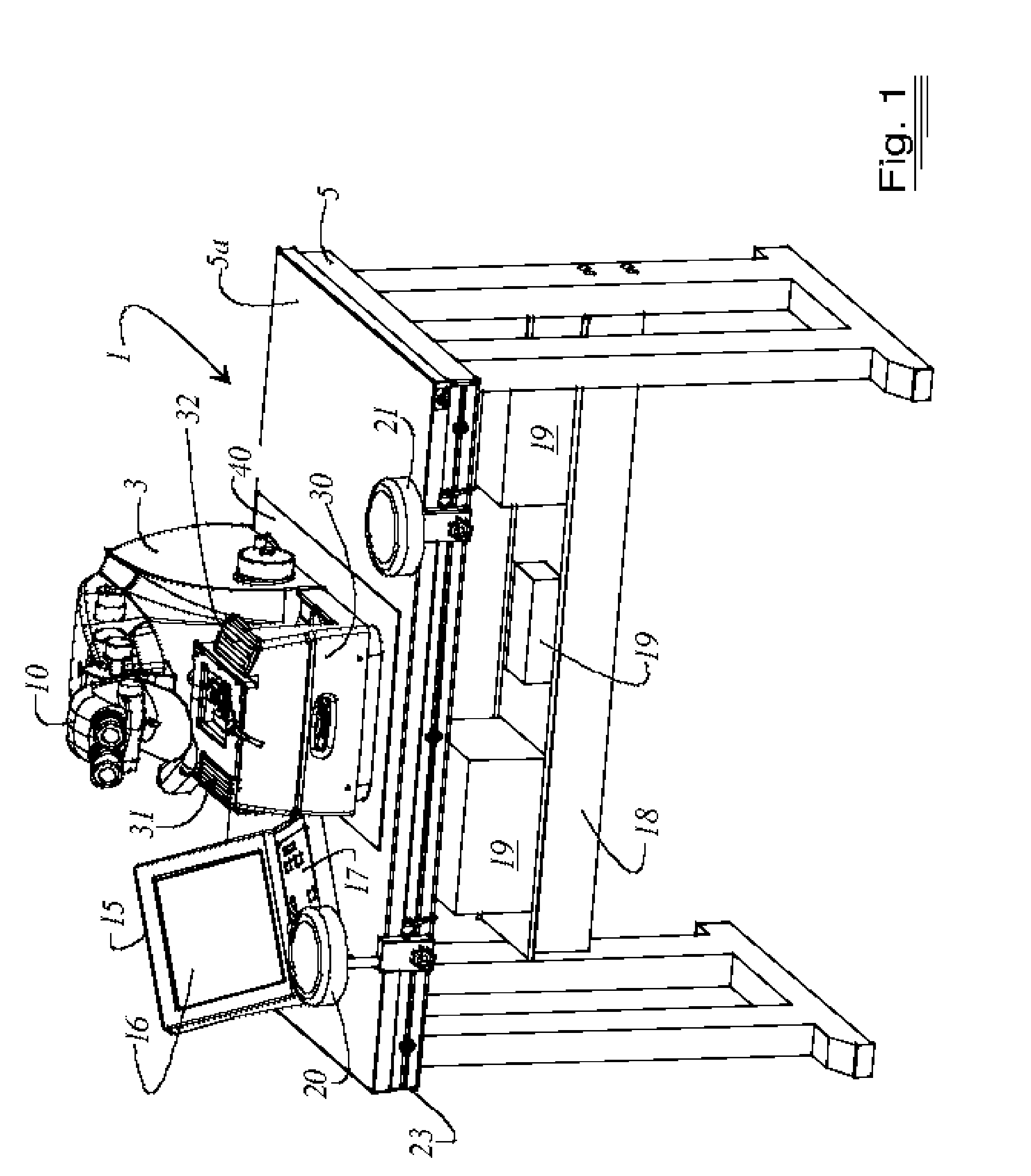
[0031]FIG. 1 is a perspective view of a device 1 for sectioning and trimming samples at low temperatures. Device 1 encompasses a sectioning apparatus 3 for generating thin sample pieces, and a cooling chamber 30 that encloses at least sample holder 7 and knife holder 9. Sectioning apparatus 3 and cooling chamber 30 are placed on a table 5. Sectioning apparatus 3 carries knife holder 9 and sample holder 7. Displaceable arm supports 20 and 21 are provided on table 5 opposite knife holder 9 and sample holder 7. Arm supports 20 and 21 are adjustable to a user's ergonomics and to a configuration of the device. Table 5 is equipped with a vibration-damping insert 40 on which sectioning apparatus 3 and cooling chamber 30 stand. A control unit 15 for controlling and regulating sectioning apparatus 3 and cooling chamber 30 is additionally provided on table 5. Control unit 15 encompasses a display 16 and an input unit 17. Provided beneath table surface 5a of table 5 is a platform 18 on which e...


PUM

PropertyMeasurementUnit
widthaaaaaaaaaa
widthaaaaaaaaaa
diameteraaaaaaaaaa

Abstract

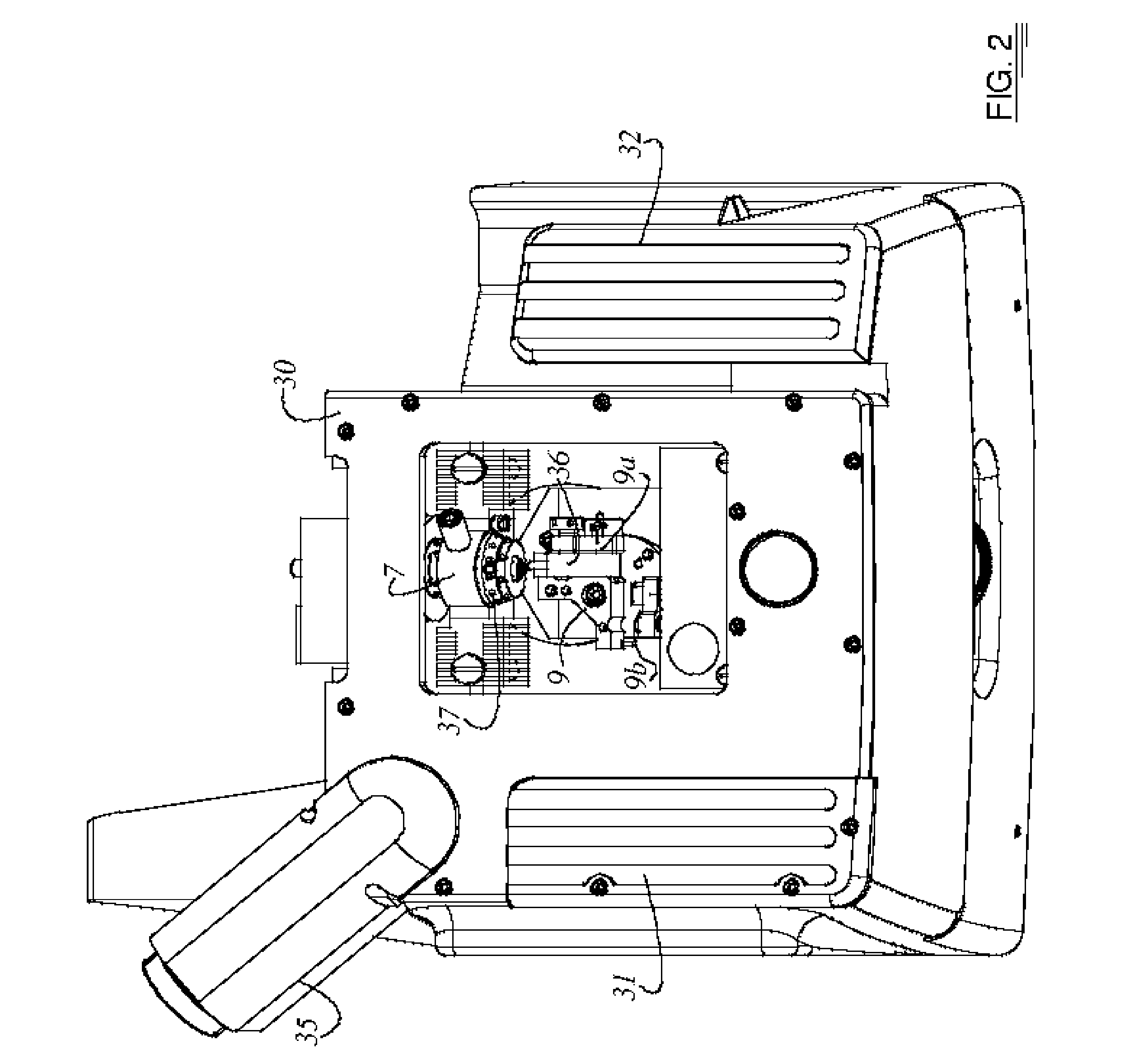
A device 1 and a method for trimming samples 38 are disclosed. The device 1 encompasses a knife holder 9 and a sample holder 7, the knife holder 9 carrying at least one trimming knife 36. A first motor 60 and a second motor 61 are provided, which move the knife holder 9 in an X-Y plane. Also provided is a control unit 15 that controls the motion of the knife holder 9. The first and the second motor 60, 61 are each equipped with a measurement means 62, 63 that measures the position of the knife holder 9 in the X direction (X) and Y direction (Y).

Description

CROSS REFERENCE TO RELATED APPLICATIONS [0001] This application claims priority of the German patent application 10 2004 001 475.2, filed Jan. 8, 2004, which is incorporated by reference herein. FIELD OF THE INVENTION [0002] The invention concerns a device for trimming samples and the invention further concerns a method for trimming samples. BACKGROUND OF THE INVENTION [0003] Microtomes and ultramicrotomes are, as a rule, equipped with at least one knife that serves for the production of thin sections of a sample. Microtomes and / or ultramicrotomes are enclosed in the region of the knife holder and the sample holder, as applicable, by a cooling chamber. The samples can then be produced in thin sections at low temperatures. Before the samples can be sectioned, they are trimmed in suitable fashion. [0004] For sectioning at room temperature, trimming machines that are equipped with a milling cutter are known from the existing art (see Leica EM TRIM brochure). With the trimming machine, ...

Claims


Application Information

Patent Timeline
Patent Type & Authority Applications(United States)
IPC IPC(8): B23D1/00G01N1/06G01N1/28
CPCG01N1/06Y10T409/50082Y10T409/500164Y10T409/303976Y10T409/303752Y10T83/141Y10T83/6508
Inventor RANNER, ROBERT
Owner LEICA MICROSYSTEMS GMBH
Learn More