Pipetting device with an ejection device for pipette tips

a technology of ejection device and pipette tip, which is applied in the direction of sampling, laboratory glassware, instruments, etc., to achieve the effect of reducing the operating force required to actuate the ejection device, limiting the mounting force of the pipette tip, and reducing the mounting for

Active Publication Date: 2005-07-21
EPPENDORF SE
View PDF26 Cites 34 Cited by
  • Summary
  • Abstract
  • Description
  • Claims
  • Application Information

AI Technical Summary

Benefits of technology

[0012] In the pipetting device according to the invention, a pipette tip is mounted by axially inserting the attachment into the mounting aperture. The mounting force is then passed into the spring. When the mounting force exceeds a specific amount, the spring is elastically deformed until the pipette tip clamped on the attachment abuts against the stop. As soon as the pipette tip bears against the stop, it can no longer be pushed further onto the attachment. As a result the mounting force of the pipette tip is limited. The mounting force is determined by the spring characteristic of the spring, or a preload of the spring which is possibly present. The spring is designed and optionally biased, such that the pipette tip bears against the stop, precisely when it is positioned with the desired mounting force on the attachment. The mounting force is established, such that the pipette tip is positioned securely on the attachment and provides a seal. As a precisely defined mounting force is reached, it is possible to limit the mounting force to a small amount, where the required certainty of the fit and the seal is precisely given. Thus the mounting force can be markedly reduced relative to conventional pipetting devices, in which an excessive mounting force is regularly used due to unreliability during mounting. Accordingly, in the pipetting device according to the invention, the operating force required to actuate the ejection device is reduced. With manually actuatable ejection devices, stresses on the tendons and muscles of the user are reduced by reducing the operating forces. Ejection devices operated electromotively manage with lower powered motors. According to an embodiment the spring is designed and / or biased such that the attachment can be displaced to such an extent toward the stop by a defined mounting force which can be applied to the attachment by mounting a pipette tip, that the pipette tip bears against the stop.

Problems solved by technology

Moreover, this favours particularly compact spring arrangements and short displacement distances of the attachment.

Method used


Image

  • Pipetting device with an ejection device for pipette tips
  • Pipetting device with an ejection device for pipette tips
  • Pipetting device with an ejection device for pipette tips

Examples


Embodiment Construction

[0054] While this invention may be embodied in many different forms, there are described in detail herein a specific preferred embodiment of the invention. This description is an exemplification of the principles of the invention and is not intended to limit the invention to the particular embodiment illustrated

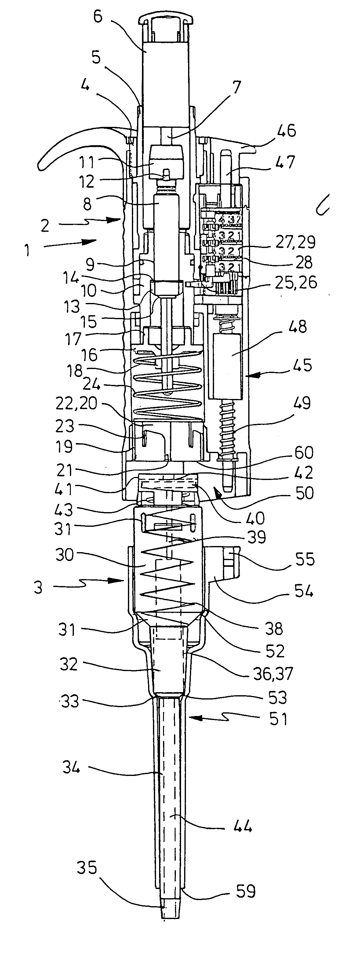
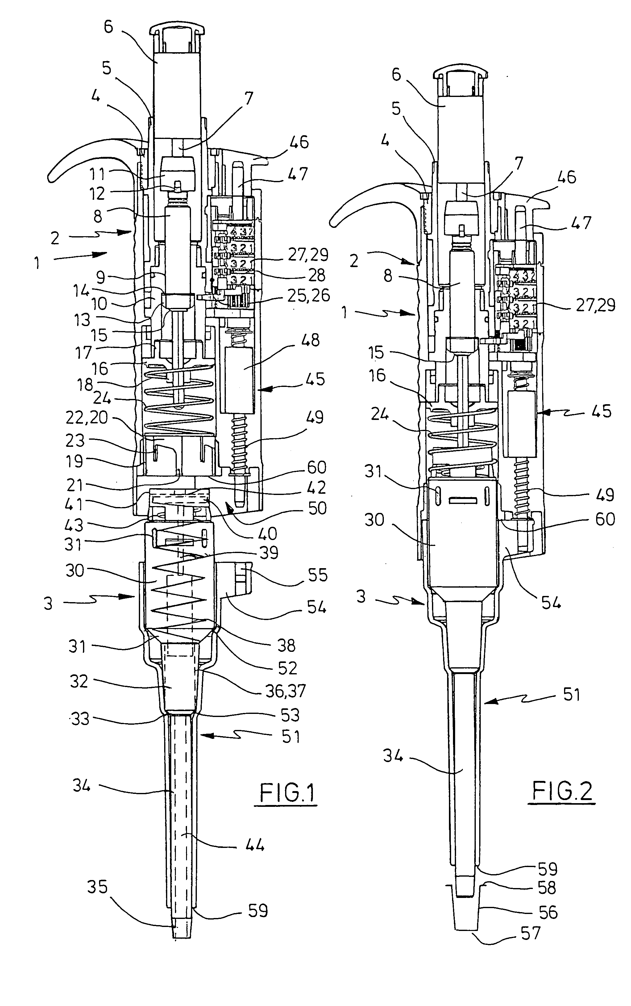
[0055] The terms ‘above’, ‘below’, ‘horizontally’, ‘vertically’, ‘front’ and ‘rear’ refer to the alignment of the pipetting device according to the drawings. In this connection it refers to alignments of the pipetting devices in which the pipette tip is arranged with its tip orifice below, in order to draw in liquid from a container located below the pipetting device and to dispense it into such a container.

[0056] The pipetting device according to FIGS. 1 and 2 has an elongate housing 1 formed as a grip with a housing upper part 2 and a housing lower part 3. The housing upper part 2 with all the parts contained therein forms a drive device and the housing lower part 3 with ...


PUM

PropertyMeasurementUnit
distanceaaaaaaaaaa
operating forceaaaaaaaaaa
forceaaaaaaaaaa

Abstract

Pipetting device with a base body, at least one attachment protruding from the base body mounted axially movably on the base body for mounting a pipette tip, a spring via which the attachment is supported on the base, a stop associated with the attachment, beyond which the attachment protrudes axially, when it is not loaded toward the spring and a throw-off device to release the pipette tip from the attachment which comprises a throw-off device associated with the attachment, the attachment and throw-off device being movable relative to one another and which comprises a drive device cooperating with the throw-off device and/or the attachment for the relative movement of the throw-off device and attachment.

Description

CROSS-REFERENCE TO RELATED APPLICATIONS [0001] Not applicable. STATEMENT REGARDING FEDERALLY SPONSORED RESEARCH [0002] Not applicable. BACKGROUND OF THE INVENTION [0003] The invention relates to a pipetting device with at least one attachment for mounting a pipette tip and an ejection device for releasing a pipette tip from the attachment. [0004] Pipetting devices are used in particular in the laboratory for metering liquids. They are drawn into pipette tips through a tip orifice and dispensed. With air cushion pipettes a displacement device for a gas is incorporated in the pipetting device and communicatingly connected to the pipette tip by the attachment. An air cushion is displaced by means of the displacement device, so that liquid is suctioned into the pipette tip and ejected therefrom. The displacement device is generally a cylinder with a piston which can be displaced therein. [0005] The pipette tips are releasably connected to the attachment, so that they can be exchanged af...

Claims


Application Information

Patent Timeline
Patent Type & Authority Applications(United States)
IPC IPC(8): B01L3/02
CPCB01L3/0279B01L2300/026B01L2200/087B01L2200/0689
Inventor BELGARDT, HERBERT
Owner EPPENDORF SE
Why Eureka
Try Eureka