Pressure sensor mounting using a molded seal

a technology of pressure sensor and molded seal, which is applied in the direction of engine seals, fluid pressure measurement by mechanical elements, instruments, etc., can solve the problems of reducing the mounting and reducing the mounting force of pressure sensors. , to achieve the effect of simplifying the mounting of molded seals, and reducing the mounting force of pressure sensors

Active Publication Date: 2007-09-20
ROBERT BOSCH GMBH
View PDF6 Cites 9 Cited by
  • Summary
  • Abstract
  • Description
  • Claims
  • Application Information

AI Technical Summary

Benefits of technology

[0004] According to the present invention, a pressure sensor is provided, on the sensor stem of which a molded seal may be accommodated in a form locked manner, at least one annular recess being provided on the circumference of the slender sensor stem. This at least one annular recess on the sensor stem enables the molded seal, on the inside of which is provided a bead which is complementary to the annular recess on the sensor stem, to be held axially in place on the sensor stem. The sensor stem, which is preferably manufactured as an injection molded plastic component in one piece with the pressure sensor housing, may thus be manufactured without burrs on its outer circumferential surface, thereby achieving the required sealing action. In a preferred exemplary embodiment, a further annular recess is produced on the sensor stem, which, when viewed in the axial direction of the sensor stem, lies below the aforementioned annular recess. This further, second annular recess provided on the circumferential surface of the sensor stem causes the flexible, elastic material from which the molded seal is made to be displaced into this second annular recess when the pressure sensor is mounted in the installation hole. Since the flexible sealing material of the molded seal and the radial forces generated thereby are displaceable into this recess during mounting, a significant reduction in mounting force is achievable. The at least one annular recess mentioned initially may therefore have either a rectangular, triangular or chamfered cross section, the design of which is complementary to the bead on the inside of the molded seal. To simplify mounting of the molded seal on the sensor stem of the pressure sensor, the bead on the inside of the molded seal may be chamfered. Furthermore, a shoulder which limits the at least one annular recess is provided on the sensor stem so that, particularly upon dismounting of the pressure sensor, the molded seal is supported thereon and does not slip off the sensor stem.
[0005] The second annular recess provided on the sensor stem in the preferred exemplary embodiment is preferably situated in the area of the molded seal's largest diameter. During mounting of the pressure sensor in the premounted state, i.e., after positioning the molded seal, the largest volume of sealing material is displaced into the second annular recess in the sensor stem when the pressure sensor and the molded seal placed thereon are mounted. This makes it possible to significantly reduce the mounting force of the pressure sensor. If the pressure sensor, including the molded seal provided thereon, is accommodated in the installation hole, a protrusion designed with an enlarged diameter forms on the side of the molded seal facing away from the sensor head on the bottom of the wall of a tank or container delimiting the installation hole, so that the pressure sensor is held in place in the mounting location by the molded seal, and the installation hole is sealed. When the pressure sensor is dismounted, or if, for example, an elevated pressure occurs inside a tank, the protrusion of the molded seal rests against the circumference of the installation hole, due to the undercut at the installation position. If the dismounting force or the applied pressure is increased, the sealing material of the molded seal expands in length and slides along the stem.
[0006] To enable the pressure sensor, including the premounted molded seal, to be installed in installation holes of varying axial lengths, multiple sealing lips are preferably provided on the outside of the molded seal. Due to the sealing length of the molded seal, at least two sealing lips always remain on the inner diameter of the installation hole, which is additionally sealed by the protrusion provided on the bottom of the molded seal. The molded seal, and thus also the sensor stem of the pressure sensor guided therein, is always supported on the inner diameter of the installation hole, which effectively prevents tilting and leakages induced thereby.

Problems solved by technology

The disadvantage of the pressure sensor known from U.S. Pat. No. 5,317,924 is the fact that, due to the plunger foot designed with an enlarged diameter at the lower end of the sensor stem, burr free manufacture of this sensor stem is difficult.
This is due to the fact that the sensor component, which is generally manufactured as a built in component by plastic injection molding and includes a sensor head, stem and foot, must be removed from two mold halves, and an undercut inevitably forms between the elongated sensor stem and the sensor foot, which is designed with a larger diameter.
When mounting the pressure sensor having the molded seal placed on the sensor stem in the installation hole, e.g., on the gas tank of a motor vehicle, there is the danger of the molded seal becoming compressed on the slender sensor stem on passing the protrusion designed with an enlarged diameter at the lower end of the molded seal.
If the molded seal made of an elastic material is compressed on the sensor stem, the installation hole, e.g., on the gas tank of a motor vehicle, is not adequately sealed.
The method known from U.S. Pat. No. 5,317,924 for mounting a pressure sensor having a molded seal in an installation hole does not achieve a completely satisfactory state, due to the disadvantages described above.

Method used


Image

  • Pressure sensor mounting using a molded seal
  • Pressure sensor mounting using a molded seal
  • Pressure sensor mounting using a molded seal

Examples


Embodiment Construction

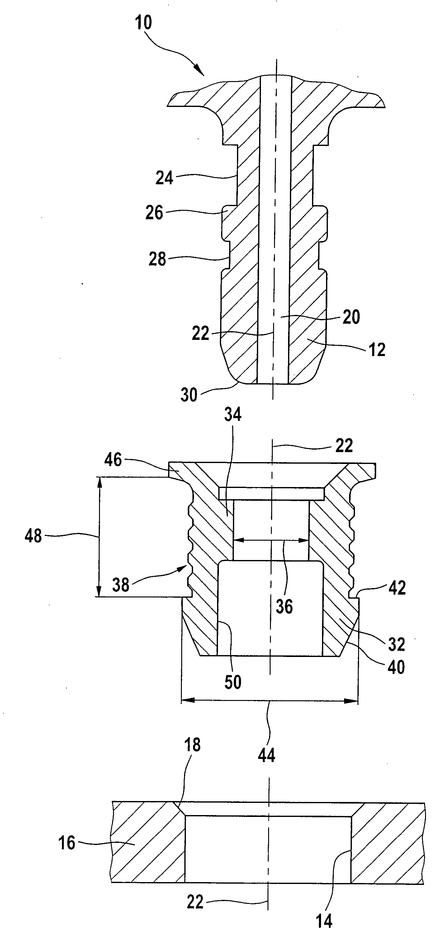
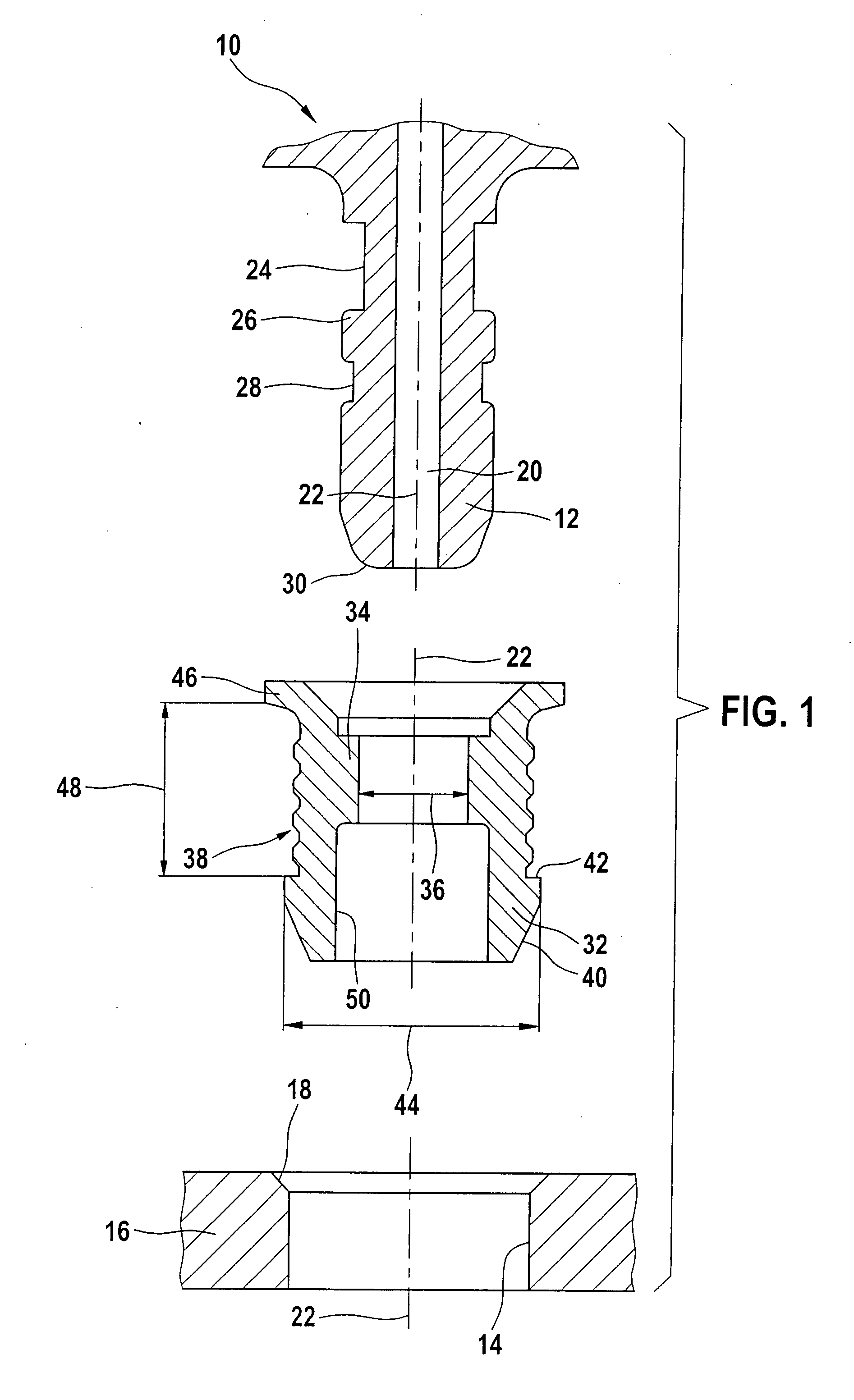
[0012] The representation according to FIG. 1 shows an exploded drawing of the sensor stem, the elastic molded seal, and the installation hole.

[0013] In the representation according to FIG. 1, pressure sensor 10, which is only partially shown, has a slender sensor stem 12 in which a sensor channel 20 is provided symmetrically in relation to the sensor's axis of symmetry 22. Pressure sensor 10 and sensor stem 12 are preferably manufactured as a one piece component by plastic injection molding. At least one annular recess 24 and preferably also a further, second annular recess 28 are formed on the circumferential surface of sensor stem 12. The at least one first annular recess 24 is delimited by a shoulder 26 on the circumferential surface of sensor stem 12. Viewed in the axial direction, the length of the at least one first annular recess 24 on sensor stem 12 is dimensioned to be greater than the length of further, second annular recess 28 preferably provided on sensor stem 12. In t...


PUM

PropertyMeasurementUnit
diameteraaaaaaaaaa
circumferenceaaaaaaaaaa
outer diameteraaaaaaaaaa

Abstract

A pressure sensor including a molded seal. With the aid of the molded seal the pressure sensor is held in place in an installation hole and seals the latter. The molded seal is attached to a sensor stem in a form locked manner. The molded seal is made of an elastic material and has, on its end facing away from the sensor head, a protrusion whose diameter exceeds the diameter of the installation hole. At least one annular recess is provided on the circumference of the sensor stem.

Description

BACKGROUND INFORMATION [0001] In the case of pressure sensors which are used, for example, on the gas tanks of motor vehicles, molded seals are used to simplify installation of the pressure sensor. These molded seals not only provide a seal for the mechanical interface between the pressure sensor and its installation hole in a wall, but also a means for mounting the pressure sensor in the installation location. The use of a molded seal makes it possible to avoid complex mounting of the pressure sensor via a mounting flange. U.S. Pat. No. 5,317,924 describes a pressure sensor which is mounted in an installation hole via a molded seal. The pressure sensor includes a sensor head and a slender sensor stem formed thereon, in which a channel is provided. A sensor foot designed with a larger diameter is situated at the end of the sensor stem facing away from the sensor head. In mounting the molded seal on the sensor stem, a through opening in the molded seal is widened to the extent that t...

Claims


Application Information

Patent Timeline
Patent Type & Authority Applications(United States)
IPC IPC(8): G01L19/00G01L19/16
CPCG01L19/0007
Inventor FESSELE, THOMASGEBAUER, JANOTT, MARCELL
Owner ROBERT BOSCH GMBH
Why Eureka
Try Eureka