Multi-component pipette tip and associated methods

Inactive Publication Date: 2008-04-03
SORENSON BIOSCI
View PDF28 Cites 52 Cited by
  • Summary
  • Abstract
  • Description
  • Claims
  • Application Information

AI Technical Summary

Benefits of technology

[0015]As used in this disclosure, the term “compliant” refers to physical properties that comply with the requirements of a fluid-tight seal. Materials exhibiting varying degrees of elasticity, resilience, hardness and related properties will be relatively more compliant or more rigid. In the context of this invention, the degree of rigidity required for a tip to be suitable for manipulation in a t

Problems solved by technology

The insertion of a cylindrical probe into such a tip creates an interference fit.
In practice, the taper of the passageway in the pipette tip does not reliably effect precise sealing and alignment of the pipette tip with the probe.
In addition, the force needed to load the pipette tip on the probe is not reliably consistent.
The annular deformation of the pipette tip required to accommodate movement of the tip onto the shaft sufficiently to create a fluid-tight seal with lateral stability is difficult to achieve and requires a large axial mounting force.
The tips of each manufacturer are correlated, by details of construction, to selected probes; they are thus not suitable for use on non-correlated probes.
An ineffective seal may result.
Unique insertion and

Method used


Image

  • Multi-component pipette tip and associated methods
  • Multi-component pipette tip and associated methods
  • Multi-component pipette tip and associated methods

Examples


first embodiment

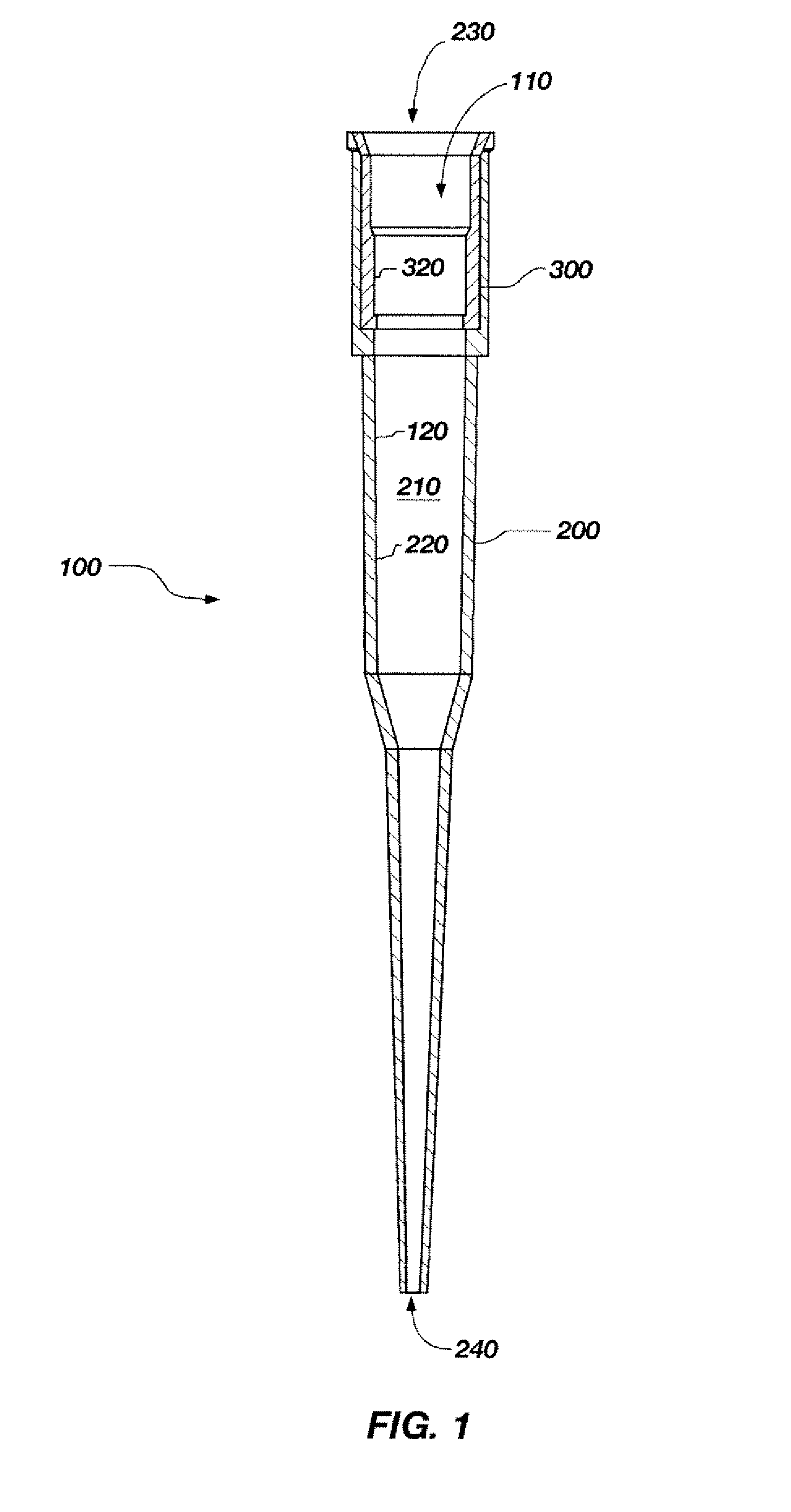
[0029]FIG. 1 depicts a pipette tip, generally 100, of the present invention. The pipette tip 100 comprises a hollow, elongated, tapered body 200 (also “outer component 200”) with a proximal open end 230 for receiving and releasably mating with a mounting shaft of a manual or mechanical pipette device (see FIG. 7C).

[0030]The pipette tip 100 comprises two components respectively formed of materials selected for their distinct but different properties. An outer component 200, shown as a hollow, elongated, tapered body, telescopically receives an inner component 300. For convenience of description, the outer component 200 is referred to as “tapered.” Within the context of this disclosure, however, the term “tapered” refers to an overall reduction in diameter throughout the length of the body. The outer component 200 may, in practice, include cylindrical segments. In any case, outer component 200 has an interior wall 220 defining an inner passageway 210. The proximal open end 230 of oute...

second embodiment

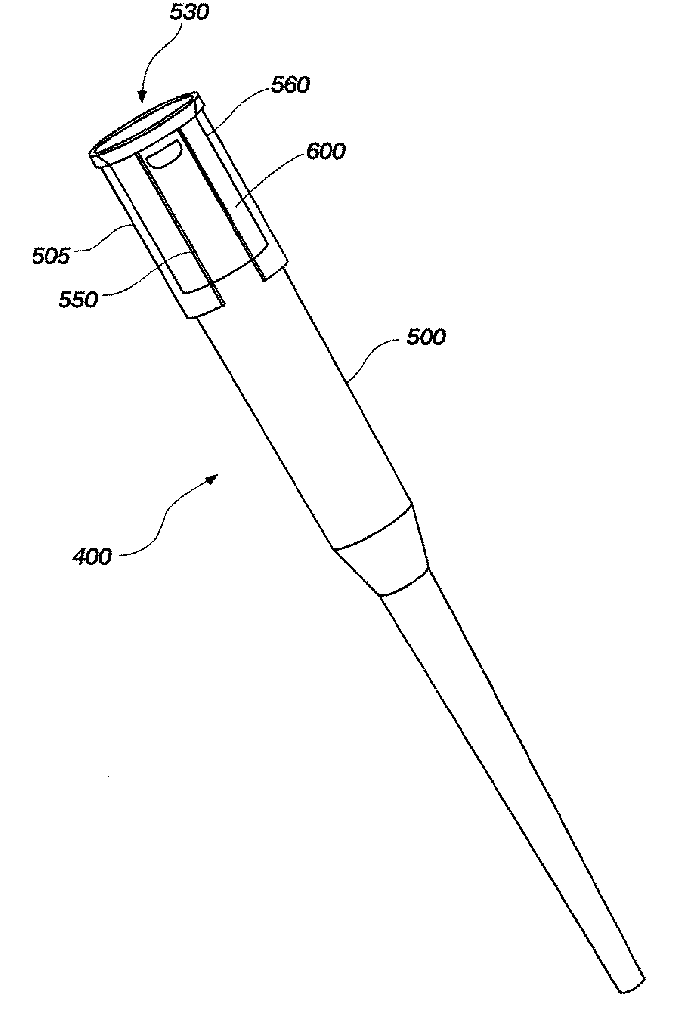
[0034]a pipette tip of the present invention is shown in FIG. 4. The pipette tip 400 includes an outer component 500 and an inner component 600. The outer component 500 includes circumferentially spaced longitudinally extending fins 550 on the outer surface 505. The fins 550 provide lateral stability. The outer component 500 further includes circumferentially spaced apertures 560 about a first open end 530 thereof. The apertures 560 may be useful for the formation of the pipette tip 400, as described in further detail subsequently in this disclosure.

[0035]The inner component 300, 600 may comprise an elastomer, such as a rubber, a foam, a thermoplastic elastomer (TPE), or a thermoplastic vulcanizate. A TPE combines the look, feel and elasticity of conventional thermoset rubber with the processing efficiency of a plastic. The melt-processability makes it suitable for high-volume injection molding and extrusion. One suitable thermoplastic vulcanizate is sold under the trade name SANTOP...

third embodiment

[0039]FIG. 5 depicts a pipette tip 450 of the present invention. The pipette tip 450 comprises at least two components. The two components shown are formed of different materials having correspondingly different physical properties. The outer component 570 comprises a hollow, elongated, tapered body, with a portion of a second, annular inner component 580 received telescopically therein. The outer component 570 has an interior wall 572 defining a passageway 571. A first, proximal end segment 575 of the outer component 570 has an opening greater in diameter than the opening of a second, distal end segment 574. The segment 575 is configured to receive a first end segment 585 of the inner component 580. A second end segment 587 of the inner component 580 is configured to receive the mounting shaft of the pipette device. The segment 574 of the outer component 570 is configured to draw a liquid into the passageway 501. The segment 587 of the inner component 580 protrudes beyond the outer...


PUM

PropertyMeasurementUnit
Diameteraaaaaaaaaa
Moldableaaaaaaaaaa
Stiffnessaaaaaaaaaa

Abstract

Described are pipette tips and methods of making the same. The pipette tips may include at least two components, an annular component and a tubular body component. The annular component may comprise a different and relatively more compliant material. The annular component may be partially or entirely telescopically received within the tubular body component. Alternatively, the annular component may comprise a proximal end of the pipette tip and the tubular body component may comprise a distal end of the pipette tip. A portion of the tubular body component may be telescopically received by the annular component or otherwise attached thereto. The pipette tip may be formed by first molding the annular component and next molding the tubular body component. Alternatively, the tubular body component may be molded first and the annular component may be molded within, adjacent, or about the tubular body component.

Description

CROSS-REFERENCE TO RELATED APPLICATION[0001]This application claims the benefit of the filing date of U.S. Provisional Patent Application Ser. No. 60 / 847,820, filed Sep. 28, 2006, for “TWO-PART MOLDED PIPETTE TIP” (MULTI-COMPONENT PIPETTE TIP AND ASSOCIATED METHODS), the entire disclosure of which is incorporated herein by this reference.TECHNICAL FIELD[0002]This invention relates generally to pipette tips, including methods of making or using an improved version of such tips.BACKGROUND[0003]Pipette tips are conventionally, either manually or robotically, manipulated for use individually or to register with the individual wells of well assay plates. Well assay plates comprise individual wells (analogous to miniature test tubes) organized in ranks and files in standardized patterns.[0004]To manipulate a tip, a probe may be inserted into its interior, whereby creating a physical connection between the probe and the tip. Pipette tips are typically characterized by an internal passagewa...

Claims


Application Information

Patent Timeline
IPC IPC(8): B01L3/00B29C45/00
CPCB01L3/0279B01L2200/0689B29L2031/753B29C45/1676B29K2221/003B01L2200/12
Inventor PRICE, WEST L.JENSEN, ZACKARY J.CALDWELL, TYLER W.STEED, FREDRICK C.
Owner SORENSON BIOSCI
Why Eureka
Try Eureka