Chest tube valve

a chest tube and valve technology, applied in the field of chest tube valves, can solve the problems of not being able to attend to other patients, requires extensive medical training to be properly performed, and is difficult to meet the requirements of patients, and achieves the effect of being less complian

Inactive Publication Date: 2020-05-28
SHARP MEDICAL PROD CHEST TUBE LLC
View PDF2 Cites 0 Cited by
  • Summary
  • Abstract
  • Description
  • Claims
  • Application Information

AI Technical Summary

Benefits of technology

[0014]Certain embodiments of the present invention contemplate an integrated chest tube valve comprising: a collar at an output end of the valve that defines an output aperture; a hollow elastomeric body extending from the collar to an input end, the input end possessing an elongated slit; and a chest evacuation tube possessing an inlet port and an outlet port, the inlet port adapted to drain fluid and / or air from a human chest cavity, the input end is inside of the chest evacuation tube, the collar is fixedly attached to the chest evacuation tube at essentially the outlet port, the elongated slit is in a closed configuration but is adapted to be in an opened configuration when a hollow tube is forcibly pushed through the elongated slit via the collar, the hollow tube is less compliant than the hollow elastomeric body.

Problems solved by technology

Insertion of a chest tube using this standard technique can require more than 15 minutes to accomplish by a physician, requires extensive medical training to be performed properly and can be extremely painful as it is a difficult area to anesthetize due to the intercostal nerve that runs on the bottom of every rib.
Further, while performing the procedure, the physician must attend to the patient receiving the chest tube and thus is precluded from attending to other patients.
Though there are numerous advantages to the present a state-of-the-art Heimlich Valve 270 and the assembly shown in FIG. 3D, applications in an emergency situation can be cumbersome and problematic.

Method used


Image

  • Chest tube valve
  • Chest tube valve
  • Chest tube valve

Examples


Embodiment Construction

[0034]Initially, this disclosure is by way of example only, not by limitation. Thus, although the instrumentalities described herein are for the convenience of explanation, shown and described with respect to exemplary embodiments, it will be appreciated that the principles herein may be applied equally in other types of situations involving similar uses of an integrated chest evacuation tube and valve system. In what follows, similar or identical structures may (and may not) be identified using identical callouts.

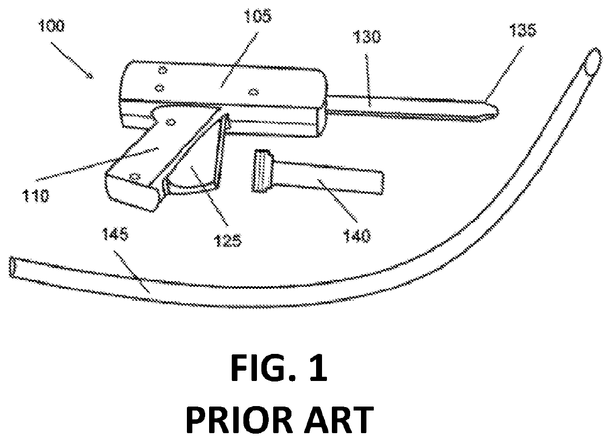
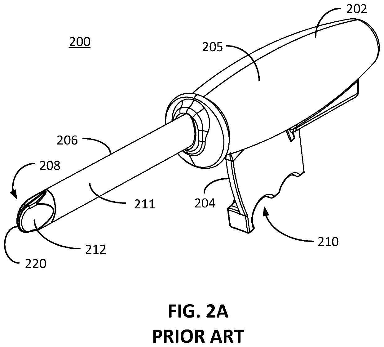
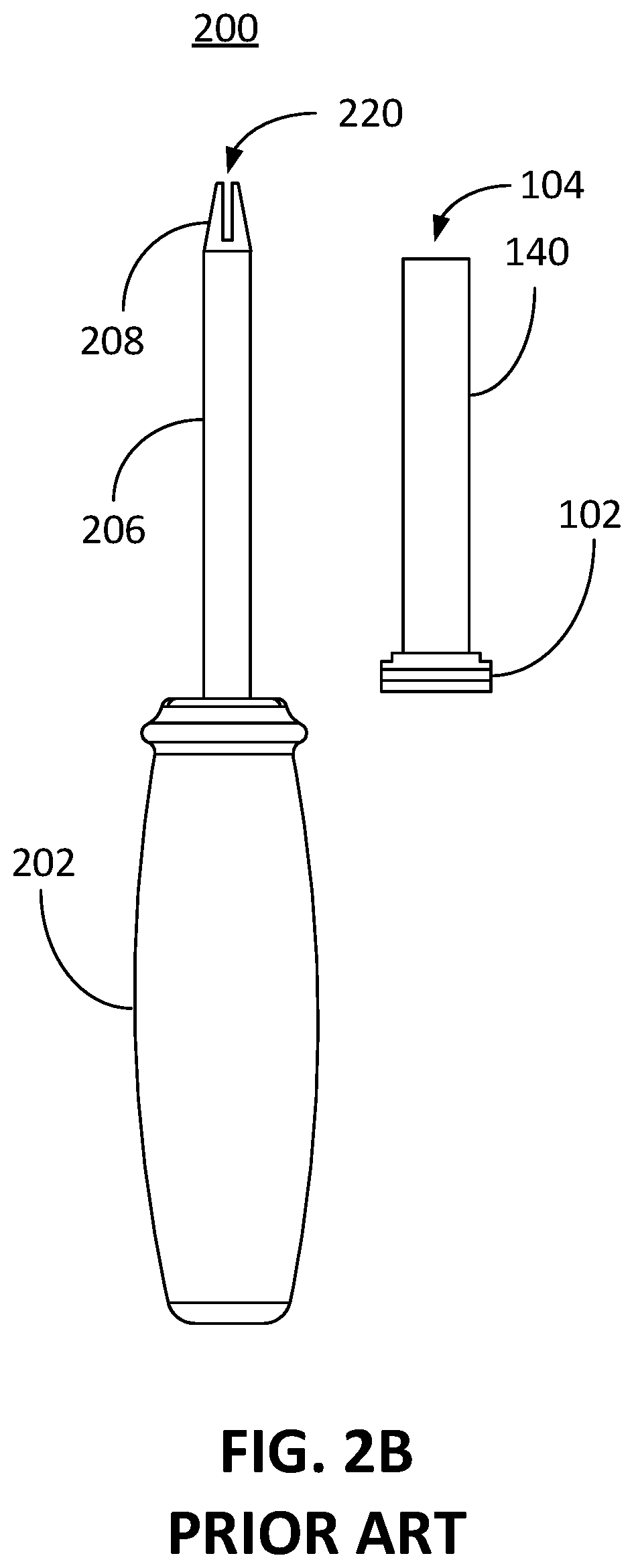
[0035]Described herein are embodiments of an integrated chest evacuation tube specifically configured as a closed system (i.e., preventing fluid / air from unintentionally escaping through the chest evacuation tube subjecting medical providers to body fluids) when inserted and retained inside of a chest cavity. The embodiments of the closed-system chest evacuation tube described herein provide enhanced benefits over the present state of the art. For example, the commonly use...


PUM


Abstract

An integrated chest evacuation tube that is specifically configured for being a closed system when inserted and retained inside of a chest cavity provides enhanced benefits over the state of the art. The integrated chest evacuation tube generally includes a valve that is made up of a hollow elastomeric housing having a collar at an output end of the housing which provides an aperture into the housing, a valve input end at an input end of the housing, and an elongated slit at the valve input end. The slit is configured to close together in a spring-like manner when in a closed position. The valve is integrated and at least partially inside of a chest evacuation tube that has a tube inlet port and a tube outlet port. The tube inlet port is adapted to drain fluid and/or air from a human chest cavity. With the collar fixedly attached to the chest evacuation tube at essentially the tube outlet port, the elongated slit is adapted to be opened by a hollow tube when the hollow tube is forcibly pushed through the slit from a direction of the collar.

Description

CROSS-REFERENCE TO RELATED APPLICATIONS[0001]This application claims priority to and the benefit of U.S. Provisional Patent Application No. 62 / 771,953 entitled: Chest Tube Valve, filed on Nov. 27, 2018.FIELD OF THE INVENTION[0002]The present embodiments are directed to an integrated chest evacuation tube and valve system with some applications being used with a chest tube insertion device.DESCRIPTION OF RELATED ART[0003]The lungs are surrounded by a pleural sac made up of two membranes, the visceral and parietal pleurae. The parietal pleura lines the thoracic wall, and the visceral pleura surrounds the lung. The pleural space is a potential space between these two layers of pleurae. It contains a thin layer of serous pleural fluid that provides lubrication for the pleurae and allows the layers of pleurae to smoothly slide over each other during respiration. In abnormal circumstances, the pleural space can fill with air and certain types of fluids not normally present requiring drain...

Claims


Application Information

Patent Timeline
Patent Type & Authority Applications(United States)
IPC IPC(8): A61M1/04A61M39/12
CPCA61M2039/2433A61M39/12A61M1/04A61M2039/2426A61M2210/101A61M1/70A61M1/84A61B17/32
Inventor SALVINO, CHRISHART, KEIRHUSEMAN, MARK J.
Owner SHARP MEDICAL PROD CHEST TUBE LLC
Why Eureka
Try Eureka