
Compliant osteosynthesis fixation plate

a technology of fixation plate and osteosynthesis, which is applied in the field of prosthetic implants, can solve the problems of metal plate system being miniaturized and more biocompatible, affecting and affecting the use of metal, so as to maintain the structural rigidity of the device, retain enough structural rigidity and strength, and alter the physical characteristics of the prosthesis

Active Publication Date: 2005-04-21
DSM IP ASSETS BV
View PDF21 Cites 30 Cited by
  • Summary
  • Abstract
  • Description
  • Claims
  • Application Information

AI Technical Summary

Benefits of technology

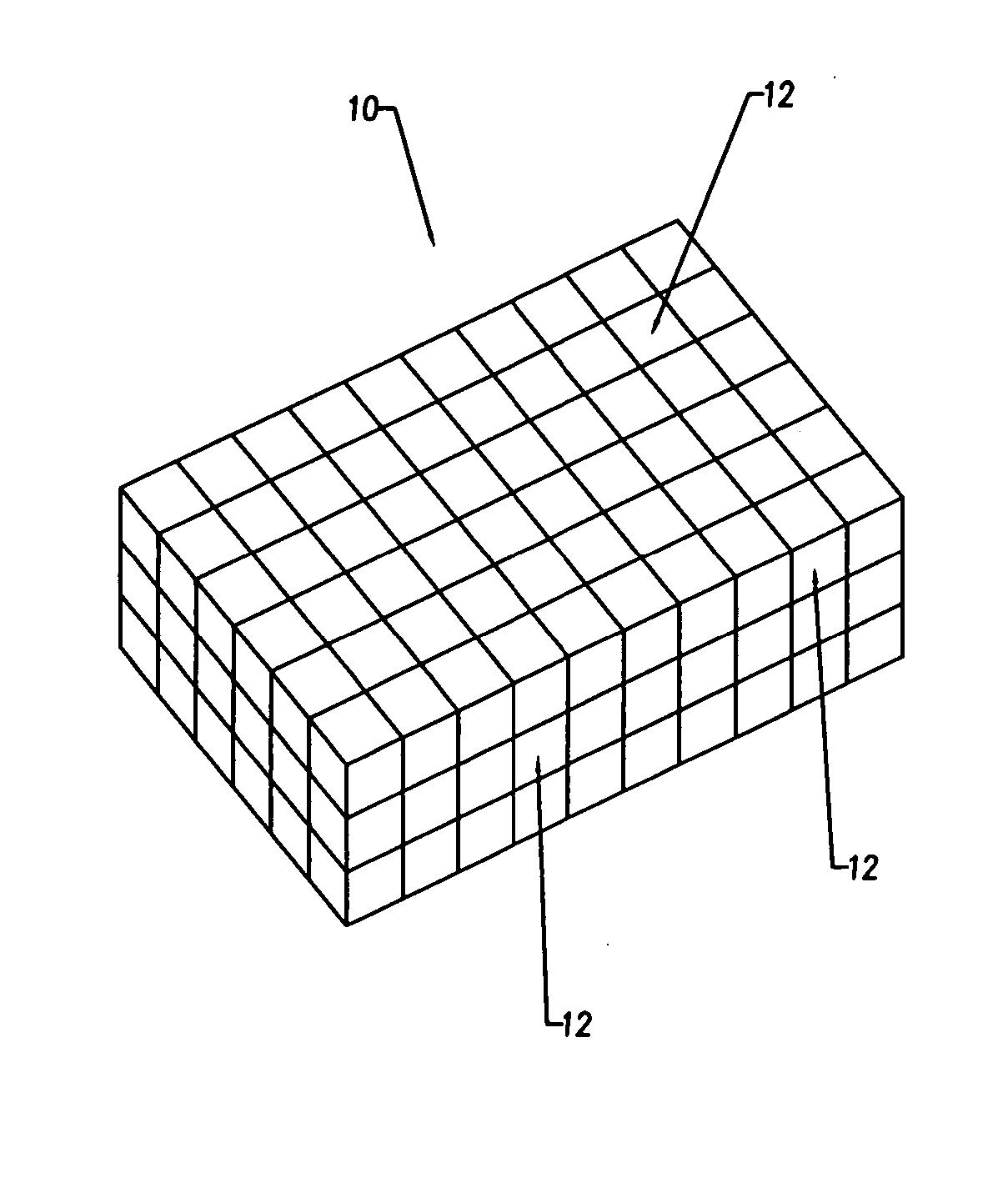
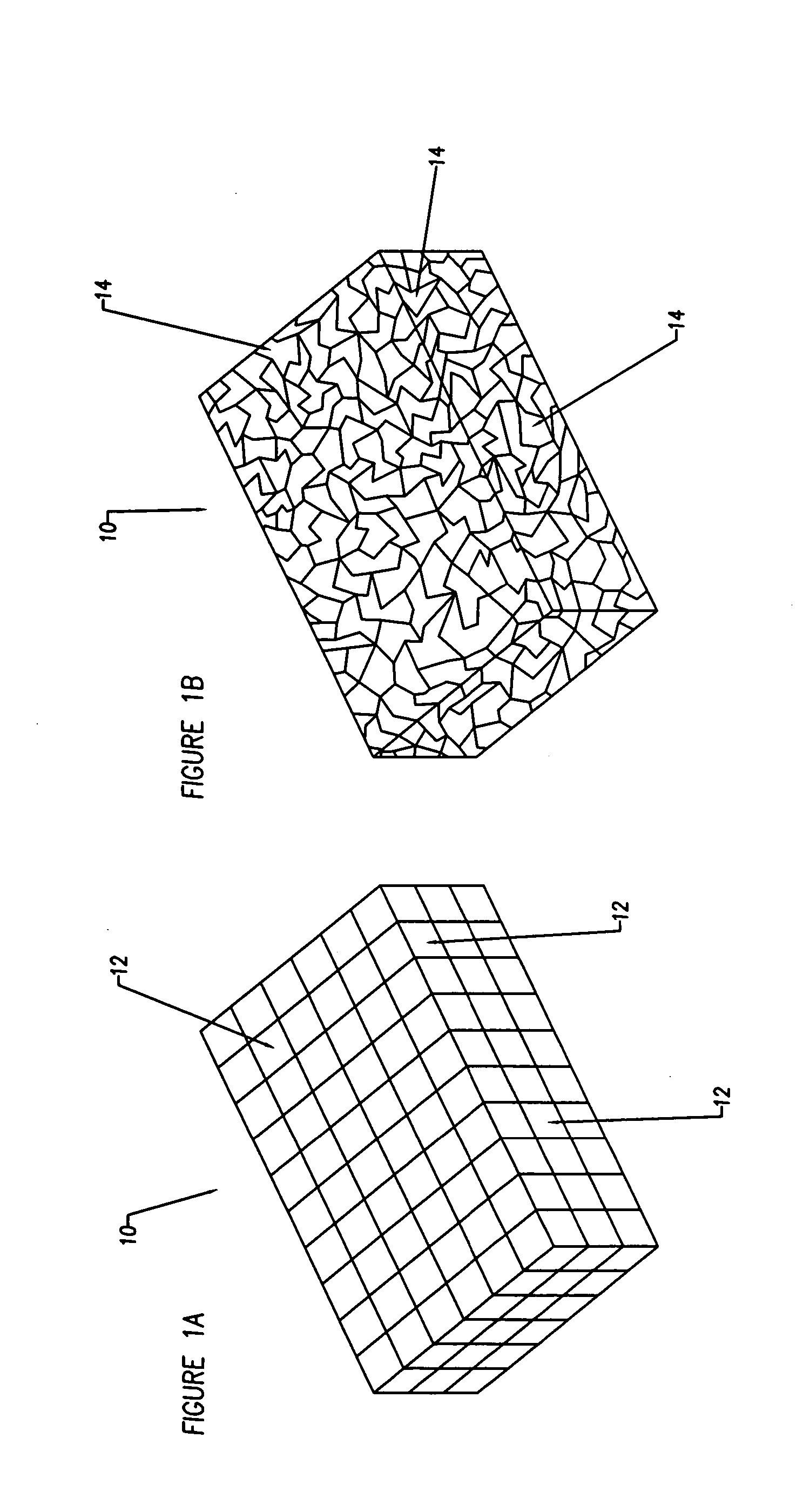
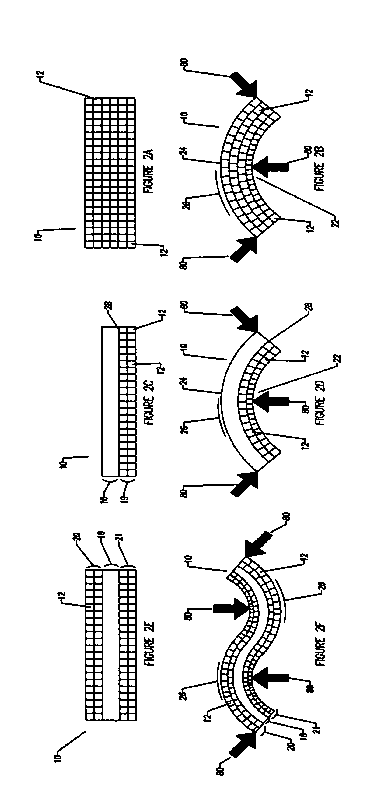
[0029] The present invention takes advantage of the porous structure of the prosthesis that allows deformation of the device without cracking or breaking of the structure. When bending pressure, for example, is applied, individual pores will collapse, allowing the smooth bending of the prosthesis in a radius, rather than a sudden collapse of the material as the prosthesis breaks. Similarly, if compressive force is applied, a portion of the pores may collapse, allowing the prosthesis to conform to the shape of the tissue it is pressed against, while maintaining the structural rigidity of the device.
[0030] While allowing the flexibility to be custom fit to the patient's tissue contours at room temperature in the operating field without special tools, the prosthesis retains enough structural rigidity and strength to lend structural support and protect a healing wound of a patient, e.g., to serve as a tissue or bone fixation device, a skull plate, or other prosthesis requiring structural rigidity. By altering the construction, such as varying the pore size and number or incorporating reinforcement materials, the physical characteristics of the prosthesis can be altered. In this fashion, a tissue fixation device, e.g., a bone plate, that is more compliant and having controlled structural stiffness due to incorporated pores may be manufactured. A tissue fixation device as described may be useful as a skull plate for example, where less flexing or stress is to be expected. Alternatively, by reducing the size and number of pores, a more rigid, and less compliant plate can be manufactured. Such a prosthesis would be more suitable for higher stress uses, including immobilizing bone fragments for broken ribs, pelvis, arms or legs as non-limiting examples.
[0031] The present invention is distinguishable from the prior art of porous tissue replacement devices, as the tissue replacement devices of the prior art serve to replace tissue temporarily, even so much as mimicking the tissue architecture replaced, and encourage the ingrowth of blood and tissue to allow new tissue growth to replace the bioeroding prosthesis. In contradistinction, the present invention serves to immobilize or hold two tissue areas together, functioning as a tissue-joining device, and does not require the ingrowth of new tissue as the device bioerodes. The device of the present invention is capable of being bent or altered without requiring any extraneous steps, such as heating or embossing of the device.
[0032] These and other objects of this invention are achieved by providing a biodegradable prosthesis, the prosthesis being made of a porous polymer foam material or alternatively a composite of a porous polymer foam material and a reinforcing material. The prosthesis being capable of room temperature bending, yet retaining sufficient rigidity and strength to lend structural support and allow healing while in use. The unique use of pores within the current invention provides advantages over previously existing solid polymer and metal bone fixation plates, such as:
[0036] 4) Pores allow for superior anchorage when using glues / adhesives.
[0046] 14) Device can be bent or shaped without deformation of preexisting anchorage holes.

Problems solved by technology

Over the years, metallic plate systems have become miniaturized and more biocompatible.
Despite the utility of metallic plate systems, their use is not without problems.
Multiple bending attempts may be required to achieve a desired fit, potentially fatiguing the metal.
Furthermore, an extended customization and shaping process may lead to higher risk for the patient, due to a protracted period while under anesthesia, as well as increased opportunity for infection.
Metal plates have the drawback of remaining in place long after the healing process is complete, unless removed through a second invasive procedure.
This intransience may be harmful where there is a need for continued bone growth and that growth is restrained by the implant, e.g., a child's skull must be capable of continued growth through development, and a metal skull plate, if left in place after cranial surgery, would interfere with developmental growth.
Other postoperative complications from metallic plating systems include: visibility or palpability, hardware loosening with resulting extrusion (e.g. “screw backout”), temperature sensitivity to cold, screw migration and maxillary sinusitis, bone atrophy or osteopenia caused by stress shielding and corrosion, interference with radiographic imaging and radiation therapy, allergic reactions, intracranial migration in cranio-orbital surgery, and the possibility of causing growth restriction of the craniofacial skeleton on pediatric patients.
Additionally, a metal prosthesis, if not removed after healing, may over time corrode or allow the leaching of metals to other locations of the body.
Additionally, any problems commonly associated with metal implants that may also be associated with resorbable implants, such as bone atrophy, would be transient, as the problem would not persist beyond the absorption of the implant.
One disadvantage of injection molding, however, is that the polymer may undergo a relatively long heat cycle, which breaks down the molecular weight of the polymer, thereby, affecting material strength as well as degradation characteristics.
Another major disadvantage to injection molding is that there will usually be a certain amount of inherent stress within the plate due to freezing the polymer in place prior to it obtaining the orientation of lowest energy.
In the case of heat application, the screw holes of the plate have been shown to become distorted causing some screw points to become unusable or preventing proper thread contact and alignment.
This is an additional heating step and can lengthen a manufacturing process or further break down the molecular weight of the polymer.
Disadvantages to this method include an even longer heating cycle than injection molding, a slow process that is difficult to use on a large scale, and a process that may require machining the holes into the fixation plate as a second operation.
The materials derived from ordinary thermal molding techniques (injection and compression molding) are not flexible at room temperature.
After heating, the physician has only a limited amount of time, often just seconds, in which to accomplish the bending.
This additional time increases anesthesia requirements and operating room time and increases the potential of infection.
The repeated heating, if necessary, to allow careful molding of the prosthesis adds to the time and complexity and cost of the procedure, further increasing the risk to the patient.
Furthermore, if the prosthesis is not properly heated above the glass transition temperature as required for flexibility, and is bent while below the glass transition temperature, then the prosthesis will remain inflexible or be rather brittle, and likely develop cracks and / or micro-cracks upon bending.
The deformation process adds to the cost of manufacturing the tissue fixation device, adding to required labor and time of manufacture.
A multi-piece kit, such as described by Pollock, would necessarily result in waste as the unused sizes and shapes of the kit would be discarded as not being appropriate for the specific patient's needs.

Method used


Image

  • Compliant osteosynthesis fixation plate
  • Compliant osteosynthesis fixation plate
  • Compliant osteosynthesis fixation plate

Examples


Embodiment Construction

[0055] The object of the invention is an implantable prosthesis, constructed of a porous, resorbable, polymer material. The material comprising the prosthesis or device (as used herein, the terms prosthesis and device are used interchangeably) is a resorbable polymer that is biocompatible with the systems of a living being. The construction of the prosthesis is such that it is to be capable of easily being shaped. The shaping may occur in a variety of manners, such as by bending or compressing to conform to a desired shape without requiring any source of heating or special tools, and upon removal of the bending or shaping force, the prosthesis will remain in the exact shape, or nearly so; thus enabling the prosthesis to fit the unique contours of each patient. Despite being easily manipulated by hand, the prosthesis remains rigid and strong enough to lend structural support, and allows protection to the wound of a living being while the healing process occurs. The device has several...


PUM

PropertyMeasurementUnit
resorbableaaaaaaaaaa
lengthsaaaaaaaaaa
biocompatibleaaaaaaaaaa

Abstract

A bendable polymer tissue fixation device suitable to be implanted into a living body, consisting of a highly porous body, made from a polymer, the porous body having a plurality of pores, such that the device is capable of being smoothly bent, wherein the bending collapses a portion of the pores to form a radius curve, and the polymer fixation device is rigid enough to protect a tissue from shifting. Preferably, the polymer fixation device may be capable of being gradually resorbed by said living body. In one embodiment, the polymer fixation device consists of a plurality of layers distinguishable by various characteristics, such as structural or chemical properties. In another embodiment, the polymer fixation device may feature additional materials which serve to reinforce or otherwise alter the structure or physical characteristics of the device, or alternatively the additional materials serve to deliver therapies to the living being.

Description

CROSS-REFERENCE TO RELATED APPLICATIONS [0001] This application is a Continuation-In-Part of U.S. patent application Ser. No. 10 / 619721, filed on Jul. 15, 2003, entitled Compliant Osteosynthesis Fixation Plate which is assigned to the same assignee as this invention, and whose disclosure is incorporated by reference herein.FIELD OF THE INVENTION [0002] The invention generally relates to prosthetic implants, specifically relating to resorbable prosthetic implants. The invention more particularly concerns a resorbable osteosynthesis fixation plate. Specifically, an implant for joining tissue or bone fragments of the cranium, face and other plastic / reconstructive procedures. BACKGROUND OF THE INVENTION [0003] Rigid internal fixation has been indicated for treatment of defects of the mammalian skeletal system for decades. Although external fixation such as plaster and splints have been used to stabilize the skeleton since ancient times, it was not until the emergence of steel wire in th...

Claims


Application Information

Patent Timeline
Patent Type & Authority Applications(United States)
IPC IPC(8): A61B17/00A61B17/80A61L31/04A61L31/12A61L31/14A61L31/16A61L31/18
CPCA61B17/80A61B2017/00004A61L31/04A61L31/125A61L31/146A61B17/8085A61L31/16A61L31/18A61L2300/00A61B17/8061A61L31/148
Inventor RINGEISEN, TIMOTHY A.
Owner DSM IP ASSETS BV
Learn More