Method of manufacturing a filament formed reinforcement member and a run flat tire support therewith

a technology of filament formation and filament reinforcement, which is applied in the field of pneumatic tires, can solve the problems of increased manufacturing complexity, inability to meet the requirements of the customer, so as to maintain the needed structural rigidity and ensure the effect of rigidity

Inactive Publication Date: 2006-01-24
THE DOW CHEM CO
View PDF99 Cites 6 Cited by
  • Summary
  • Abstract
  • Description
  • Claims
  • Application Information

AI Technical Summary

Benefits of technology

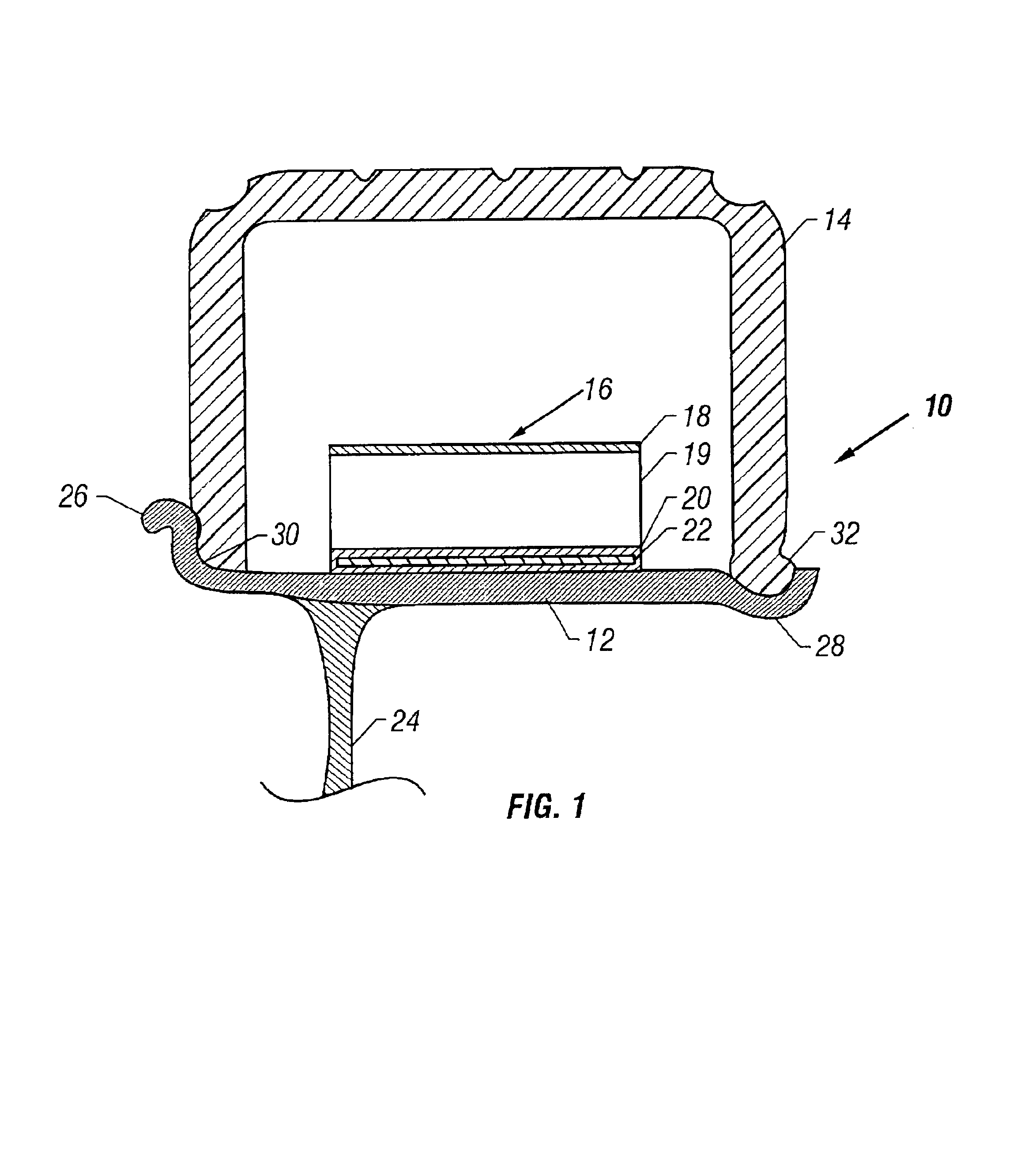
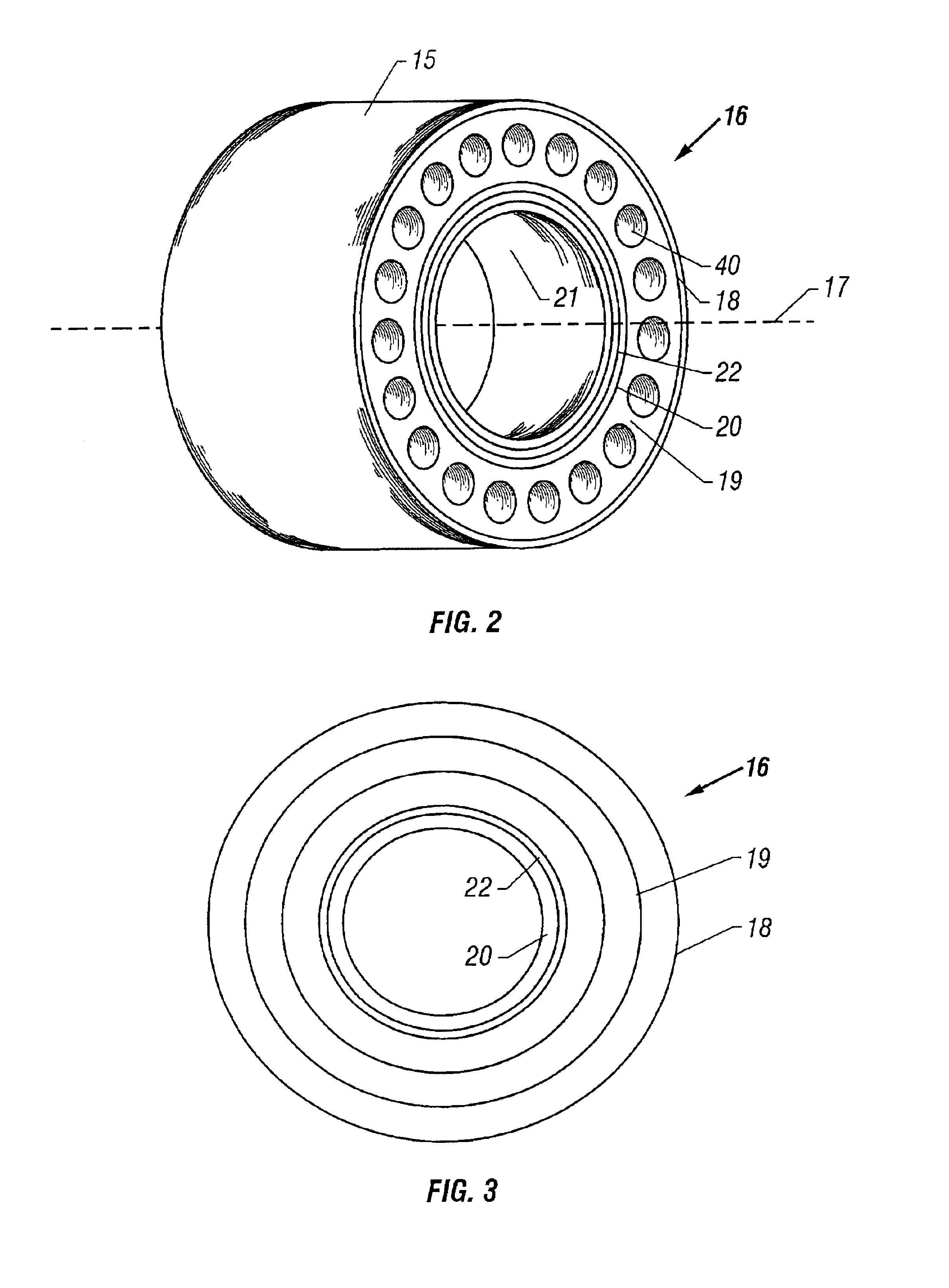
[0012]The present invention provides a unitary run flat tire (RFT) support reinforcement that is formed from a filament material into a relatively rigid shape. Generally, the unitary RFT support reinforcement can be formed from multiple layers that are coupled together, such as with an adhesive, to form one effective layer. The one effective layer can include layers of filaments wound into a reinforcement. The reinforcement is insertable into a mold for an RFT support and can maintain the needed structural rigidity for such insertion. The RFT reinforcement can have a rigidity sufficient to deform about 20% or less when dropped from about two meters high to a hard surface when an axis of the RFT reinforcement is substantially perpendicular to gravity.

Problems solved by technology

A challenge in manufacturing the support is to provide adequate structural integrity to have sufficient strength, so that outwardly directed centrifugal forces do not substantially deform the RFT support during rotational use.
Prior to the present invention, there did not appear to be a profitable production method of manufacturing RFT reinforcements that were suitable for quick placement.
However, use of standardized scrim cloth can lead to increased manufacturing complexities.
Further, the reinforcement insertion time can be relatively long, if the reinforcement is so flexible that it does not have a stable shape or a compact thickness for ease of insertion into the channel.
Aligning the several layers of openings can add complexities to the process and tooling.
Also, the flexible cloth-type of reinforcement is generally produced in individual units and adds cost to the support.
Loft can cause difficulty in inserting the material into narrow mold cavities.
Also, multiple layers of scrim cloth or other reinforcement material can add difficulties in inserting the multiple layers into the mold, if the layers are decoupled from each other or become delaminated during use.

Method used


Image

  • Method of manufacturing a filament formed reinforcement member and a run flat tire support therewith
  • Method of manufacturing a filament formed reinforcement member and a run flat tire support therewith
  • Method of manufacturing a filament formed reinforcement member and a run flat tire support therewith

Examples


example 1

RFT Reinforcement Formation and Rigidity Test Filament Wound RFT Reinforcement with Coating

[0135]A unitary, rigid RFT reinforcement was prepared using a filament winding system. The filament wound RFT reinforcement was constructed similar to the construction shown in FIG. 4 having transverse members and circumferential members. Generally, the filaments were wound around about a 50 cm diameter mandrel, a binder coating applied to the filaments and cured to form a tubular member having one effective layer, and the tubular member cut into one or more RFT reinforcements.

[0136]More particularly, the filament wound RFT reinforcement was made from 450 yield, that is, about 450 yards per pound, fiberglass and a binder, such as an epoxy Derakane® resin was applied. The binder and fiberglass yield can vary. The RFT reinforcement tubular member was made on a filament winding machine that utilizes a computer program to wind the fiberglass filament around a steel mandrel. For this example, the m...

example 2

RFT Reinforcement Formation and Rigidity Test Filament Wound Reinforcement with Coating

[0142]An RFT reinforcement was prepared from fiberglass filament by passing the filament through an epoxy resin bath and then winding the filament onto a 48 cm diameter mandrel using a computer-controlled filament winding machine. The mandrel was placed in an oven at about 70° C. for one hour to cure to form one effective layer. The resulting filament wound tube was removed from the mandrel and cut into about 8 cm long sections using a band saw. The fiberglass content of the resulting RFT reinforcement was about 62% and about 35% binder applied to the fiberglass filament. The RFT reinforcement had a weight of about 550 grams per square meter. In at least one embodiment, the manufactured RFT reinforcement has a mass of about 160 grams to about 200 grams with about 180 grams being an average. The values of density, mass, and other parameters are exemplary and non-limiting and can vary as appropriate...


PUM

PropertyMeasurementUnit
timeaaaaaaaaaa
widthaaaaaaaaaa
weight percentaaaaaaaaaa

Abstract

The present invention provides a unitary run flat tire (RFT) reinforcement using filament material that is formed into a relatively rigid shape. The reinforcement is insertable into a mold for an RFT support and can maintain the needed structural rigidity for such insertion. Further, the invention provides an RFT support that is molded and includes the RFT reinforcement. The invention also provides a wheel assembly including a tire, a rim, and an RFT support between the rim and the tire, where the support includes the RFT reinforcement. The RFT support can have a colored indicator formed or subsequently applied thereto to indicate one or more attributes of the support.

Description

[0001]This application claims the benefit of U.S. Provisional Application Ser. No. 60 / 231,658, filed Sep. 11, 2000; Ser. No. 60 / 289,958, filed May 10, 2001; and Ser. No. 60 / 300,887, filed Jun. 25, 2001, all incorporated herein by reference.FIELD OF THE INVENTION[0002]The field of invention relates to pneumatic tires. The invention particularly relates to run flat tire supports for pneumatic tires.BACKGROUND OF THE INVENTION[0003]In past years, the automotive industry has provided spare tires for replacement of punctured or blown out tires while traveling. However, efforts have been made to eliminate the need for the spare tire by providing improved designs for tires. Specifically, efforts have been made to provide a stable and economical tire that can run with little or no pressure when, for example, the tire is flat. The term for the efforts has become known as “run flat tire” (RFT) technology. The RFT concept allows an operator to continue driving or rolling for an extended period...

Claims


Application Information

Patent Timeline
Patent Type & Authority Patents(United States)
IPC IPC(8): B60C17/00B29C45/00B29D30/04B60B21/12B29C31/04B29C35/02B29C39/02B29C39/10B29C41/04B29C45/14B29C48/05B29C48/06B29C48/08B29C48/335B29C53/60B29C53/62B29C53/80B29C67/24B29C70/16B29D30/06B29K19/00B29K105/08B29K105/20B29L30/00B60C11/24B60C15/02B60C17/04B60C17/06
CPCB29C39/028B29C39/10B29C41/045B29C45/0005B29C47/023B29C53/60B60C15/0236B60C17/04B60C17/06B29C31/04Y10T152/10738B29C47/0009B29C47/0021B29C47/003B29C47/025B29C47/20B29C47/26B29C53/62B29C53/8058B29C53/8066B29C53/8075B29C67/246B29C2793/009B29K2025/00B29K2063/00B29K2075/00B29K2105/0032B29K2105/04B29K2105/08B29K2267/00B29K2309/08B29K2995/002B29L2009/00B29L2030/00B29C35/02Y10T428/24091B60C2017/068Y10T428/24074Y10T152/10054B29C53/68B29C48/03B29C48/08B29C48/12B29C48/153B29C48/154B29C48/32B29C48/335B29C48/05B60C17/061B60C2017/063B29C48/06
Inventor TABOR, RICK L.JIMENEZ, JR., PATRICIOWILKOMM, WAYNE R.PRIESTER, JR., RALPH D.CORNELL, MARTY C.CHRISTENSON, CHRIS P.BENNETT, KIMBERLY F.DANIELSEN, PEDER E.ZAWISZA, JEFFERY D.
Owner THE DOW CHEM CO
Why Eureka
Try Eureka