Low-cost, modular high-temperature thermal energy storage system

a modular technology, applied in the field of modular high-temperature thermal energy storage systems, can solve the problems of limiting the applicability of heavy industry, increasing scarceness, and large size of heavy industry, and achieves the reduction of the relative thickness of the thermocline zone, increasing the charge and discharge efficiency, and reducing the fluid velocity in each module line

Pending Publication Date: 2021-12-16
KHALIFA UNIV OF SCI & TECH
View PDF1 Cites 0 Cited by
  • Summary
  • Abstract
  • Description
  • Claims
  • Application Information

AI Technical Summary

Benefits of technology

[0013]In another embodiment of the present invention, the thermal energy storage module or regenerator further comprises a casing which preserves structural rigidity of the thermal energy storage module or regenerator.
[0017]In another embodiment of the present invention, the thermal insulation, mounted around the thermal storage matrix, ensures high thermal energy storage efficiency by limiting heat exchange between a plurality of thermal energy storage modules and further maintains structural rigidity of the thermal storage matrix.
[0027]In another embodiment of the present invention, the thermal energy storage modules of the thermal energy storage assembly are connected in a series configuration to reduce relative thickness of a thermocline zone of the whole thermal energy storage assembly, thereby increasing charge and discharge efficiencies.
[0028]In another embodiment of the present invention, the thermal energy storage modules of the thermal energy storage assembly are connected in a parallel configuration to reduce fluid velocity in each module line, thereby reducing pressure losses.
[0032]In another embodiment of the present invention, a parallel configuration of the thermal energy storage modules of the regenerator reduces pressure losses by reducing fluid velocity in each storage module, and allows for simultaneous charging and discharging operations.

Problems solved by technology

Major drawbacks of regenerators and TES systems used in heavy industry are the large size and capital costs.
The previous technologies use exhaust gases or air because conventional thermal oil or molten salt have a limited temperature range (<400° C. for synthetic oil and <600° C. for molten salt) and present significant drawbacks (hazard classification, flammability), which limit their applicability in heavy industry.
Energy supply has always been a major issue, all the more so now that fossil fuels are becoming increasingly scarce, and with rising concerns about global warming.
Renewable energy sources are theoretically inexhaustible, so they can supply the global population for, at least, a very long time.
Indeed, this TES technology represents a high initial investment, between 15 and 20% of the total cost of the CSP plant, it is classified as hazardous (SEVESO) in Europe and has a limited working temperature range below 600° C.
However, some elements of the thermocline TES system using solid filler materials lead to limitations preventing its deployment in the industry or renewable energies sector.
First of all, the combination of a solid matrix and a low thermal capacity fluid has a direct impact on the outlet temperature and pressure drops of the TES system.
For large scale TES system, the pressure drops may be so high that they would lead to larger investments for the ventilation system and parasitical electrical overconsumption.
Secondly, adding a solid matrix creates mechanical constraints.
The combination of a large scale TES single-tank and high temperature can lead to significant extra expenditures.
Consequently, when the temperature decreases, a new mechanical constraint is created on the walls.
Finally, despite a decrease of the cost from a two-tank to a single-tank TES system, the thermocline TES system is not yet enough competitive to be deployed in the industry sector.
In addition of a specific design for each configuration, the structural elements (tank and insulation material) are costly as they have to withstand the temperature and, more importantly, the mechanical conditions due to the solid matrix.

Method used


Image

  • Low-cost, modular high-temperature thermal energy storage system
  • Low-cost, modular high-temperature thermal energy storage system
  • Low-cost, modular high-temperature thermal energy storage system

Examples


Embodiment Construction

"d_n">[0045]The aspects of the method or system to provide a modular and high-temperature thermal energy storage system which withstands temperature and mechanical conditions according to the present invention, will be described in conjunction with FIGS. 1-8. In the Detailed Description, reference is made to the accompanying figures, which form a part hereof, and in which is shown by way of illustration specific embodiments in which the invention may be practiced. It is to be understood that other embodiments may be utilized and logical changes may be made without departing from the scope of the present invention. The following detailed description, therefore, is not to be taken in a limiting sense, and the scope of the present invention is defined by the appended claims.

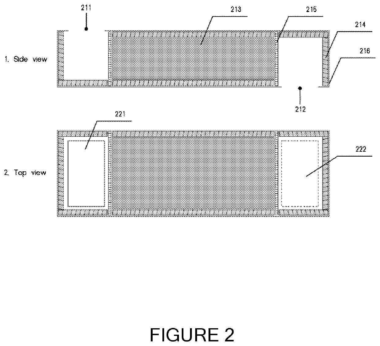
[0046]The present invention relates to a low-cost, modular and high-temperature thermal energy storage system, with a minimum temperature level of 200° C. FIG. 1 illustrates the 3-D isometric view of the thermal ene...


PUM


Abstract

There is provided a modular and high-temperature thermal energy storage system, which withstands temperature and mechanical conditions. The disclosed thermal energy storage system comprises a thermal energy storage assembly to adapt to storage capacity requirements of an energy consumer comprises a plurality of thermal energy storage modules are stacked on top of each other to increase energy storage capacity, wherein the stack of thermal energy storage modules acts as a single thermal energy storage unit. Also disclosed is a regenerator manufactured using a plurality of thermal energy storage modules comprises a first chamber to store heat from a hot source resulting in charging operation, and a second chamber to transfer the stored heat to air resulting in discharging. A parallel configuration of the thermal energy storage modules allows for simultaneous charging and discharging operations.

Description

CROSS-REFERENCE TO RELATED APPLICATIONS AND PRIORITY[0001]This patent application claims priority from PCT Patent Application No. PCT / IB2019 / 059259 filed Oct. 29, 2019, which claims priority from U.S. Provisional Patent Application No. 62 / 752,403 filed Oct. 30, 2018. Each of these patent applications are herein incorporated by reference in their entirety.FIELD OF THE INVENTION[0002]The present invention relates to the field of thermal energy storage systems, and more particularly to a modular and high-temperature thermal energy storage system.BACKGROUND OF THE INVENTION[0003]According to the US Department of Energy, the industrial sector accounts for about one-third of the world total energy consumed and consequently is responsible for about one-third of fossil-fuel-related greenhouse gas emissions. It is estimated that somewhere between 20% to 50% of industrial energy input is lost as waste heat in the form of hot exhaust gases. As the industrial sector continues efforts to improve...

Claims


Application Information

Patent Timeline
Patent Type & Authority Applications(United States)
IPC IPC(8): F28D20/00
CPCF28D20/0056F28D17/02Y02E60/14
Inventor CALVET, NICOLASHOFFMANN, JEAN-FRANCOISBELASRI, DJAWED
Owner KHALIFA UNIV OF SCI & TECH
Why Eureka
Try Eureka