Screen printer

a screen printer and printer technology, applied in the field of screen printers, can solve the problems of substrate dislocation from the clamp state, difficult to reliably hold the clamp state, and increase the equipment cost, and achieve the effect of simple and cheap mechanism and reliably held

Active Publication Date: 2005-07-21
PANASONIC CORP
View PDF10 Cites 18 Cited by
  • Summary
  • Abstract
  • Description
  • Claims
  • Application Information

AI Technical Summary

Benefits of technology

[0008] In accordance with the present invention, the warp correcting portion is arranged in the clamp member and corrects warp deformation of the substrate by abutting the warp correcting member on the upper face side of the side end portion of the substrate in the state in which the substrate is nipped by the clamp member. Th...

Problems solved by technology

However, in the above conventional screen printer, an equipment occupying area and equipment cost are increased by separately arranging the mechanism for correcting the flexure, and disadvantages of clamp dislocation explained below are easily caused.
However, in the case of the substrate of a kind tending to be ...

Method used


Image

  • Screen printer
  • Screen printer
  • Screen printer

Examples


Embodiment Construction

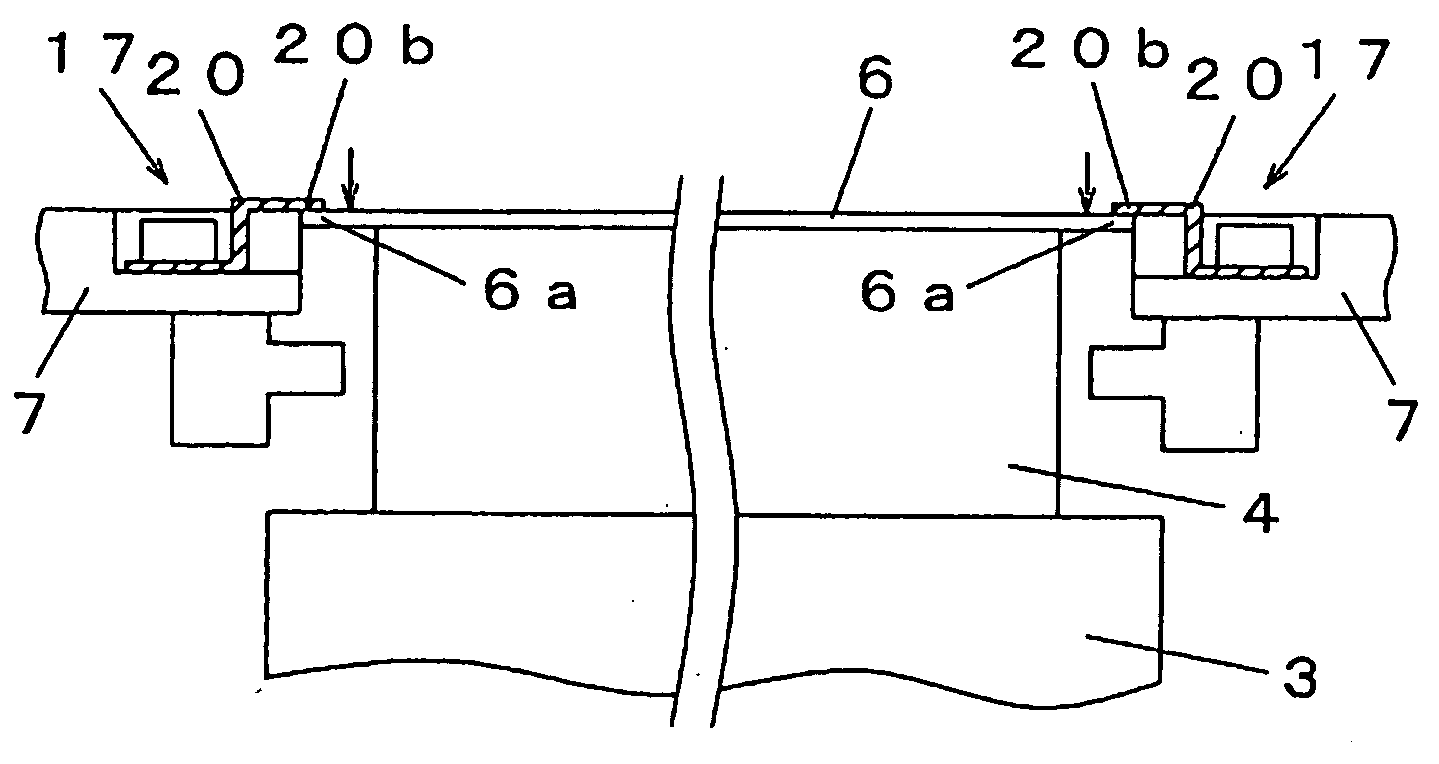
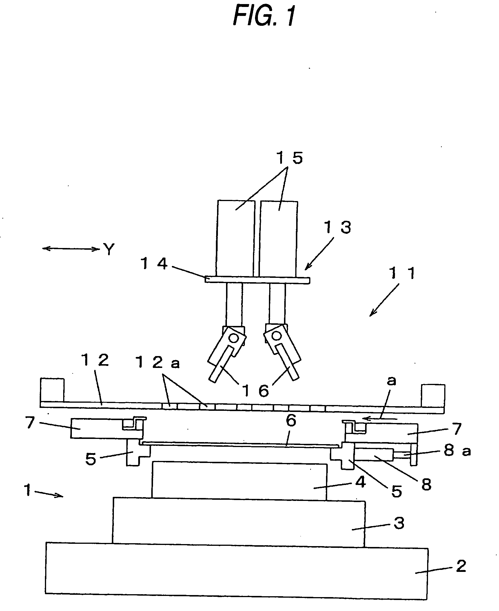
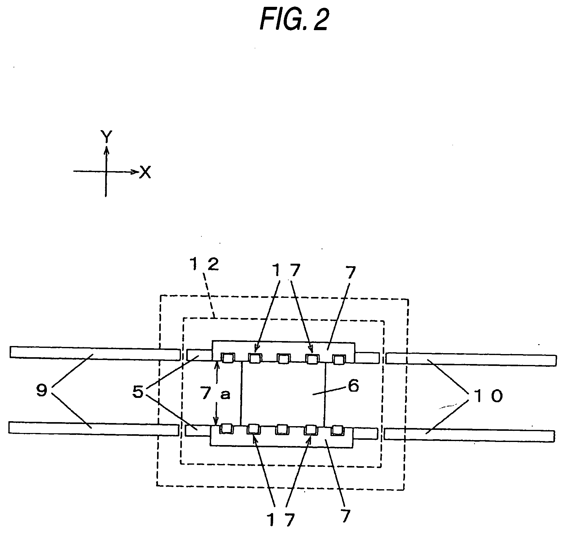
[0013] The embodiment modes of the present invention will next be explained with reference to the drawings. First, with reference to FIGS. 1 and 2, the structure of the screen printer will be explained. In FIG. 1, a substrate positioning portion 1 is constructed by stepwise stacking a Z-axis table 4 on a moving table constructed by a Y-axis table2 and an X-axis table 3. A substrate holding face for adsorbing and holding a substrate 6 is arranged on the upper face of the Z-axis table 4. Accordingly, the Z-axis table 4 constitutes a substrate holding portion for receiving the substrate 6 from the lower side and holding the substrate 6 in the substrate positioning portion 1. The position of the substrate 6 at the screen printing time can be adjusted by moving the substrate 6 held in the substrate holding portion in the X-direction and the Y-direction by controlling the operations of the Y-axis table 2 and the X-axis table 3. Further, the height of the held substrate 6 can be set to an ...


PUM


Abstract

In the screen printer for printing paste to the substrate through a pattern hole by abutting a mask plate on the substrate, the end face of a side end portion of the substrate 6 is nipped and held from its both sides by a clamper 7. A warp correcting portion 17 mounting a warp-correcting member 20 constructed by a plate-shaped resilient metal is arranged in the clamper 7. When the substrate 6 held to a substrate holding portion of a Z-axis table 4 is clamped, a free end portion 20b of the warp correcting member 20 is abutted on the upper face side of the side end portion 6a of the substrate 6, and the warp deformation of the substrate 6 is corrected by pressing the free end portion 20b downward. Thus, the warp deformation of the-substrate is corrected by a simple and cheap mechanism, and the clamp state can be reliably held.

Description

BACKGROUND OF THE INVENTION [0001] The present invention relates to a screen printer for printing paste such as cream solder, electrically conductive paste, etc. to a substrate. [0002] In a mounting process of an electronic part, screen printing is used as a method for printing paste such as cream solder, electrically conductive paste, etc. onto the substrate. In this method, a mask plate having a pattern hole arranged in accordance with a printing object part is abutted on the substrate and a squeegee is slid by supplying the paste onto the mask plate so that the paste is printed onto the substrate through the pattern hole. [0003] In the screen printing, it is necessary to closely attach the substrate to the mask plate, and correctly hold the position of the substrate so as not to cause a horizontal position shift. Therefore, a lower receiving portion abutted on the lower face of the substrate and supporting the substrate, and a clamp mechanism for nipping a side end portion of the...

Claims


Application Information

Patent Timeline
IPC IPC(8): B41F15/40B41F15/08B41F15/22B41F15/26H05K3/12H05K3/34H05K13/00
CPCB41F15/22H05K3/1216B41F15/26B41F15/14H05K3/12
Inventor SAKAUE, TAKAAKIABE, SEIKOUOTAKE, YUJI
Owner PANASONIC CORP
Why Eureka
Try Eureka