Respiratory mask assembly with magnetic coupling to headgear assembly

a mask and magnetic coupling technology, applied in the field of nasal masks, can solve the problems of significant challenges faced by prior art masks/cushions, and achieve the effects of reducing or minimizing inventory requirements and the number of differently sized masks, avoiding the application of unwanted localized pressure points, and reducing or minimizing the number of different sizes

Active Publication Date: 2005-07-21
RESMED LTD
View PDF26 Cites 341 Cited by
  • Summary
  • Abstract
  • Description
  • Claims
  • Application Information

AI Technical Summary

Benefits of technology

[0020] Another aspect is to provide a nasal mask capable of fitting a wide range of patients, so as to decrease or minimize inventory requirements and the number of differently sized masks/cushions that are required for production.
[0021] Yet another aspect of the present invention is to provide a nasal mask that offers more comfort to the patient, e.g., by better avoiding the application of unwanted localized pressure points in the facial contacting regions especially to the sensitive nasal bridge region of the patient, while maintaining a good seal, with or without the assistance of positive pressure to form or maintain the seal. Another aspect of the present invention is to avoid contact with the upper nasal bridge region, while avoiding localized pressure points along the lower nasal bridge region where the bony portion transitions into a portion of the nose containing more cartilage.
[0022] Another aspect of the present invention is to avoid application of unwanted localized contact pressure or forces that may increase undesirably the impedance of airflow through the patient's nares/naris and nasal passages, especially through the nasal vent.
[0023] Still another aspect is to provide a headgear assembly which can provide added stability to the mask/cushion assembly. In embodiments, the headgear may be made of or include at least one layer which imparts a degree of stiffness to the headstraps to assist in the stabilization of the mask/cushion assembly, which may obviate the need for a forehead support and thereby decrease visual obstructions near the patient's eyes and better enhance or at least not hinder the patient's ability to don, wear or remove eye glasses with the mask system in use. At least a portion of the headstrap itself may be formed of a relatively more rigid material in comparison to relatively flexible headstraps, instead of providing a multiple layer structure. The headgear may include a relatively large, hand-manipulab

Problems solved by technology

Some of these prior art masks/cushions has experienced significant challenges from the perspective of patient com

Method used


Image

  • Respiratory mask assembly with magnetic coupling to headgear assembly
  • Respiratory mask assembly with magnetic coupling to headgear assembly
  • Respiratory mask assembly with magnetic coupling to headgear assembly

Examples


Embodiment Construction

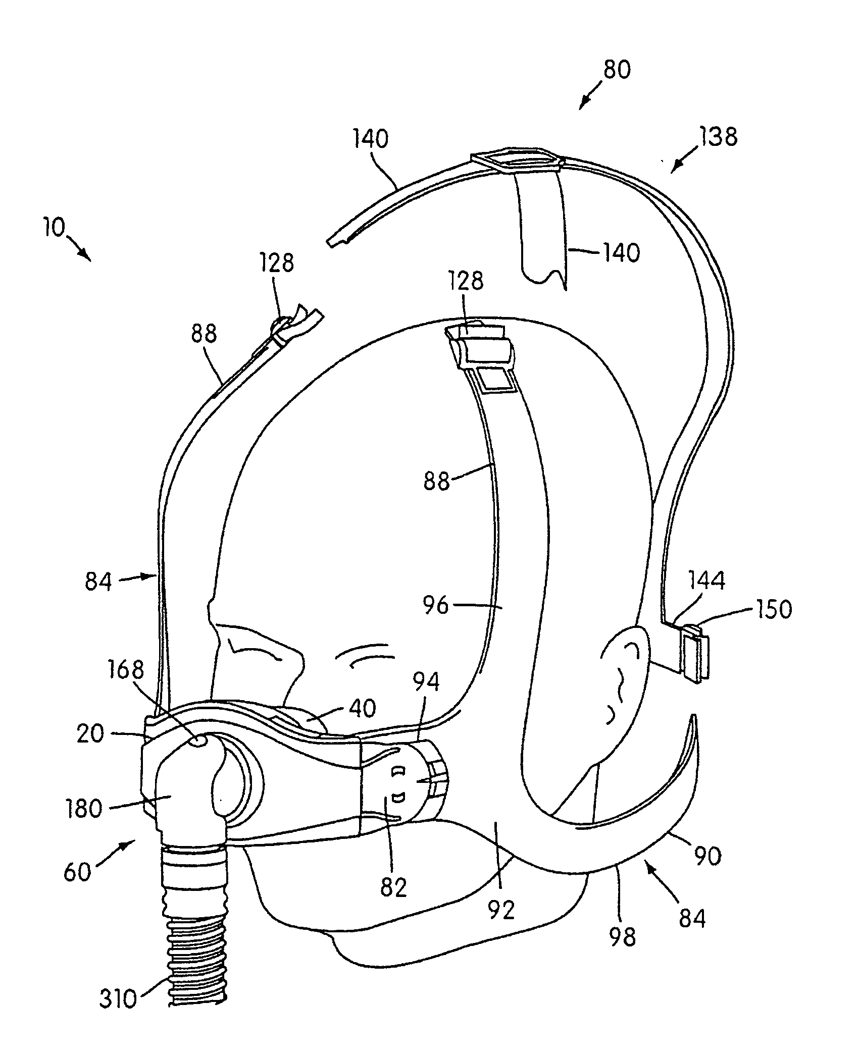
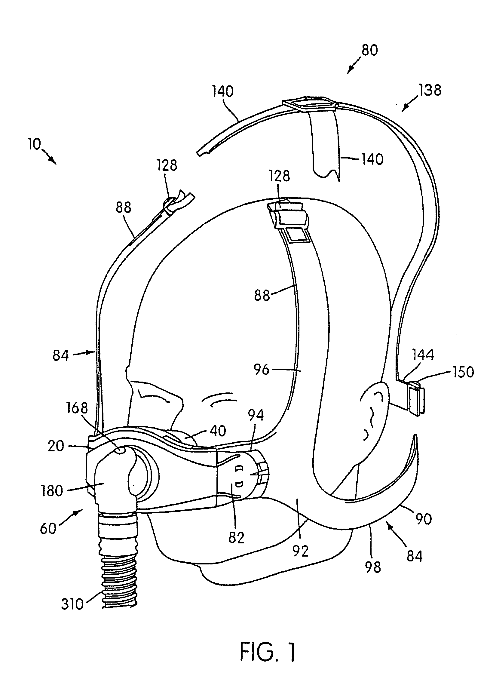
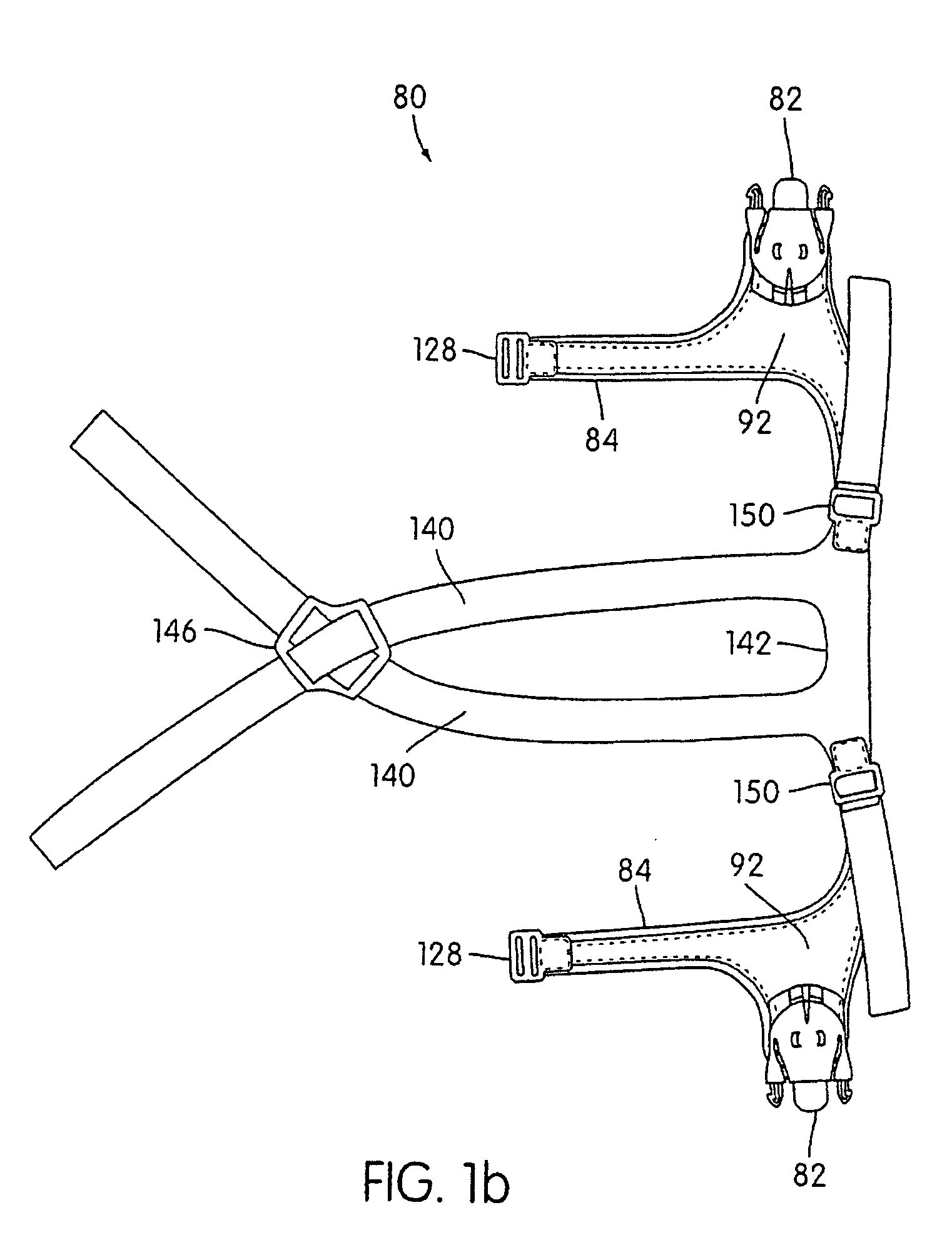
[0109] Two main embodiments are described in the figures. Although many of the features and / or parts of each embodiment are the same, there are several parts and / or elements that are different. For example, while FIG. 1 shows one embodiment of an elbow assembly 60 according to the present invention, FIGS. 6a-6b show another arrangement of the elbow assembly 60. Other differences between the embodiments will be described below. Moreover, several alternative approaches are also described with respect to various parts and / or elements, and those alternative approaches should be considered as additional preferred embodiments of the present invention.

[0110] As shown in FIGS. 1-4, a nasal mask assembly 10 according to one preferred embodiment of the present invention includes a frame 20 and a cushion 40 that is preferably detachably connected to the frame 20. Alternatively, the cushion 40 can be permanently attached to the frame 20 using, e.g., co-molding or over-molding techniques, glue ...


PUM


Abstract

A respiratory mask assembly for delivering breathable gas to a patient includes a frame and a headgear assembly which are adapted to being removeably magnetically coupled to one another at a desired angular orientation therebetween.

Description

CROSS-REFERENCE TO RELATED APPLICATIONS [0001] The present application is a continuation-in-part of commonly owned copending U.S. patent application Ser. No. 10 / 390,681 filed on Mar. 19, 2003, which in turn is based on and claims domestic priority benefits under 35 USC §119(e) from, U.S. Provisional Application Ser. No. 60 / 377,254 filed on May 3, 2002; 60 / 397,195 filed on Jul. 22, 2002; and 60 / 402,509 filed on Aug. 12, 2002, and claims foreign priority benefits under 35 USC §119(a) from Australian Application No. PS1926 filed on Apr. 23, 2002, the entire contents of each such prior-filed application being hereby expressly incorporated into the present application by reference.FIELD OF THE INVENTION [0002] The invention relates to a nasal mask for use in the delivery of Non-invasive Positive Pressure Ventilation (NPPV) and for nasal continuous positive airway pressure (nasal CPAP) therapy of sleep disordered breathing (SDB) conditions such as obstructive sleep apnea (OSA). BACKGROUND...

Claims


Application Information

Patent Timeline
IPC IPC(8): A61M16/00A61M16/06A61M16/08A62B18/02A62B18/08
CPCA44B11/266A44D2203/00A61M16/06A61M16/0683A61M16/0816A61M16/0622A61M2210/0618A62B18/084H01F7/0263A61M16/0616A61M2206/14A61M16/0875A61M16/0633A61M16/0825
Inventor GING, ANTHONY M.NASR, SAADDANTANARAYANA, MUDITHA PRADEEP
Owner RESMED LTD
Why Eureka
Try Eureka