
Hermetically sealed pressure balanced accumulator

a technology of accumulator and sealing plate, which is applied in the direction of mechanical equipment, pipe elements, pipe/joints/fittings, etc., can solve the problems of gas charge no longer acting like an ideal gas, significant pressure drop, and delay in operation, etc., and achieve the effect of improving sealing

Inactive Publication Date: 2005-07-21
EATON CORP
View PDF28 Cites 37 Cited by
  • Summary
  • Abstract
  • Description
  • Claims
  • Application Information

AI Technical Summary

Benefits of technology

The invention is a pressure-balanced accumulator with improved sealing and reduced need for recharging. It achieves this by providing a hermetically sealed accumulator with multiple balancing chambers and a first and second bellows device for sealing each chamber from the accumulator chamber. This prevents leakage between the chambers and reduces the need for recharging. The accumulator also includes a movable divider mechanism for separating the housing into different chambers and a first and second gas chamber for applying pressure to the divider mechanism. Overall, the invention provides a more effective and reliable pressure-balanced accumulator with improved performance and durability.

Problems solved by technology

In addition, if the device is located a considerable distance from the pump, a significant pressure drop can occur in the hydraulic conduit or pipe which is conveying the fluid from the pump to operate the device.
Consequently, operation may be delayed until such a time as the pressure can build up with the fluid being pumped through the hydraulic line.
Above 5000 p.s.i., however, the gas charge no longer behaves like an ideal gas.
Large changes to the ambient conditions make the accumulator less efficient overall and ultimately unable to function.
Consequently, the efficiency of conventional accumulators used in deep water is decreased.
If an accumulator is pre-charged at a surface temperature higher than the deepwater temperature, some of the pre-charge will be lost simply because the temperature was reduced.
However, in prior art pressure-balanced accumulators, the gas charge can leak into the fluid chamber, thus requiring recharging and / or causing the accumulator to become ineffective.
The process of recharging accumulators can take a significant amount of time.
For example, frequent and lengthy delays in operations, i.e. offshore drilling operations, contribute to substantial increases in the costs of those operations.
Further difficulties may arise with regard to performing preventive maintenance on the equipment, depending on the specific application.
The equipment for a particular application may be extensive in terms of components, system architecture, and complexity, and / or the accumulators may have to be removed for repair and then later reconnected.
As a result, such delays to recharge the accumulator or perform preventive maintenance may be very burdensome, time-consuming, and costly.

Method used


Image

  • Hermetically sealed pressure balanced accumulator
  • Hermetically sealed pressure balanced accumulator
  • Hermetically sealed pressure balanced accumulator

Examples


Embodiment Construction

[0030] Aside from the preferred embodiment or embodiments disclosed below, this invention is capable of other embodiments and of being practiced or being carried out in various ways. Thus, it is to be understood that the invention is not limited in its application to the details of construction and the arrangements of components set forth in the following description or illustrated in the drawings.

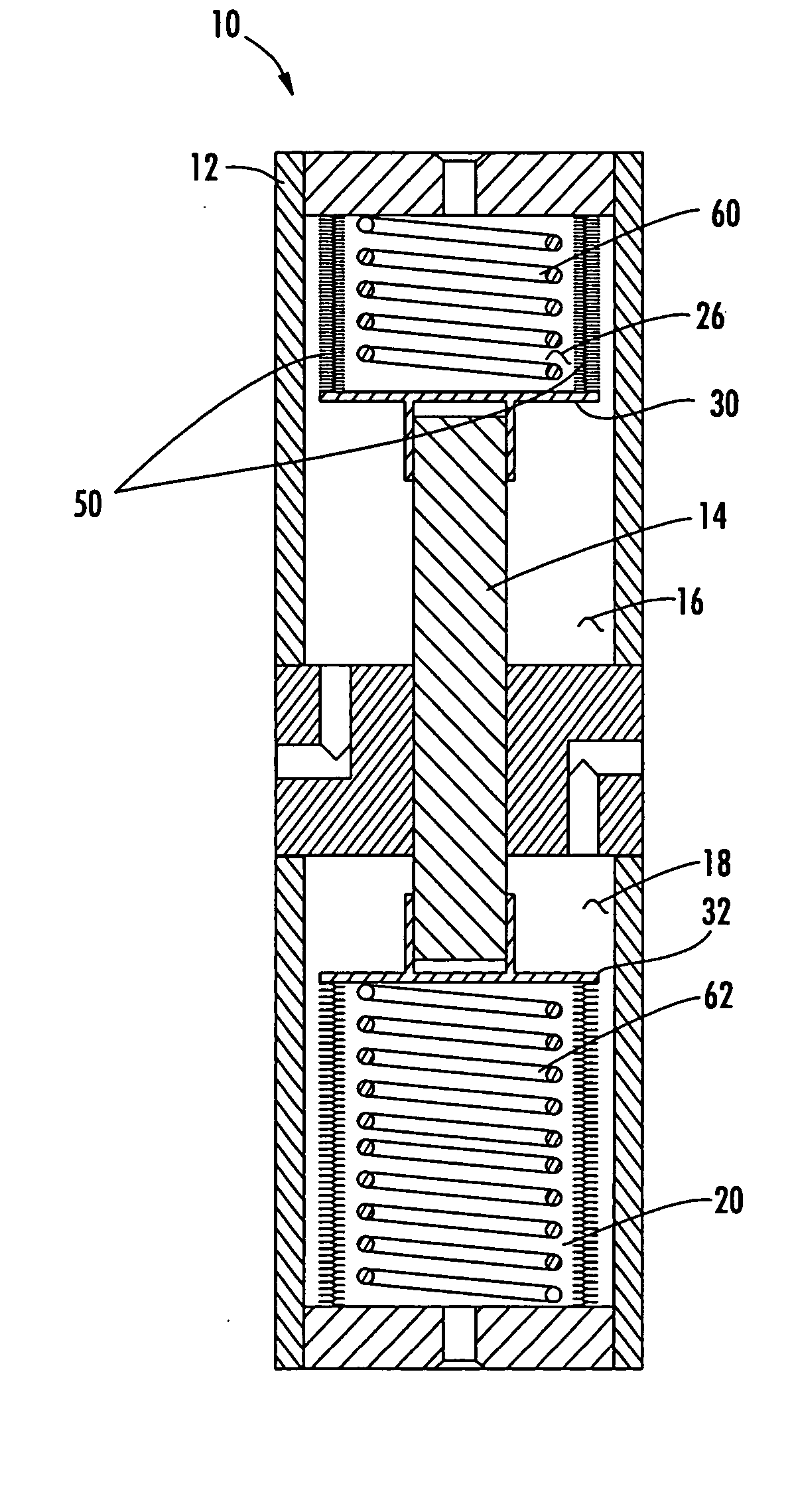
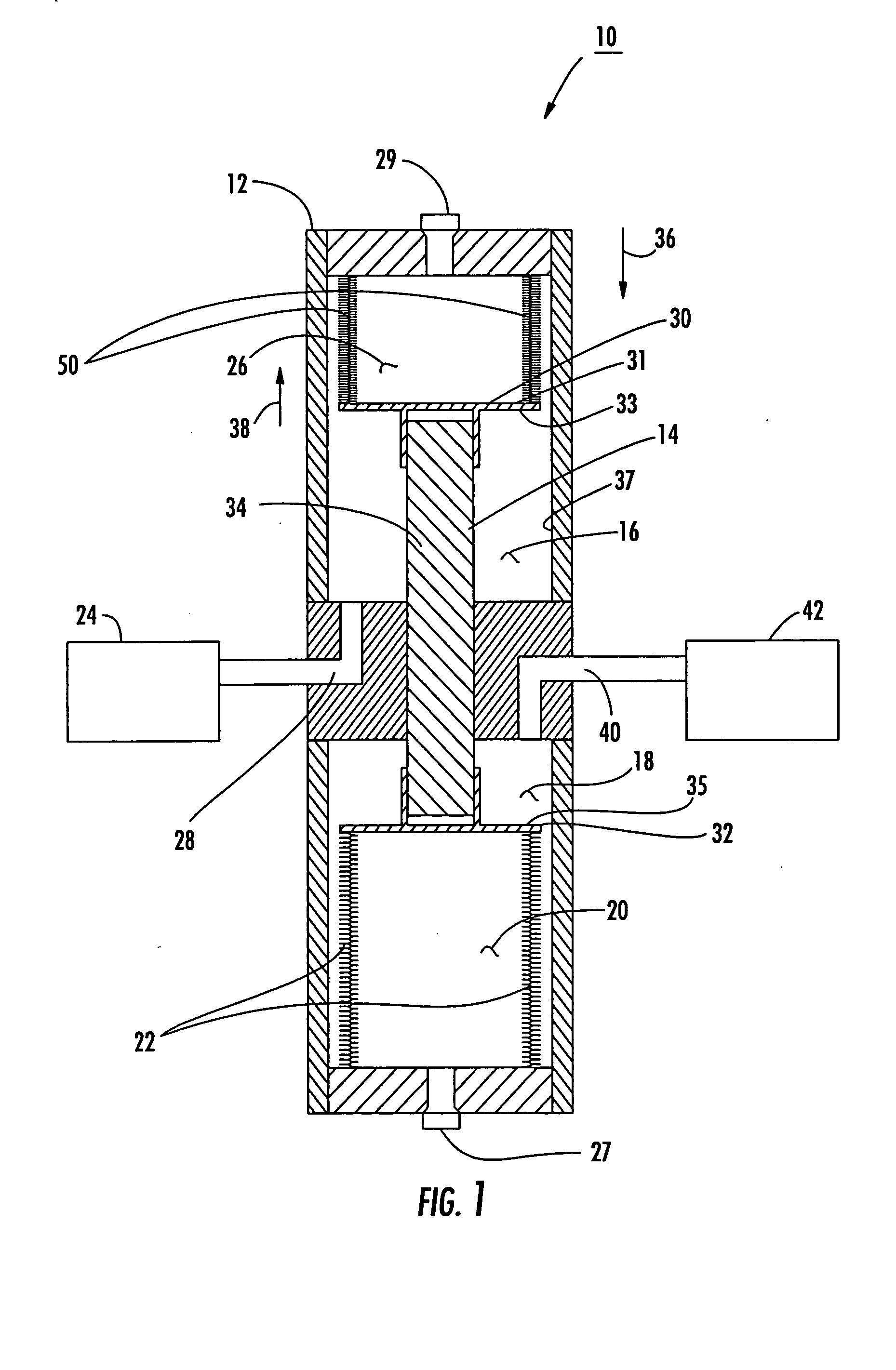
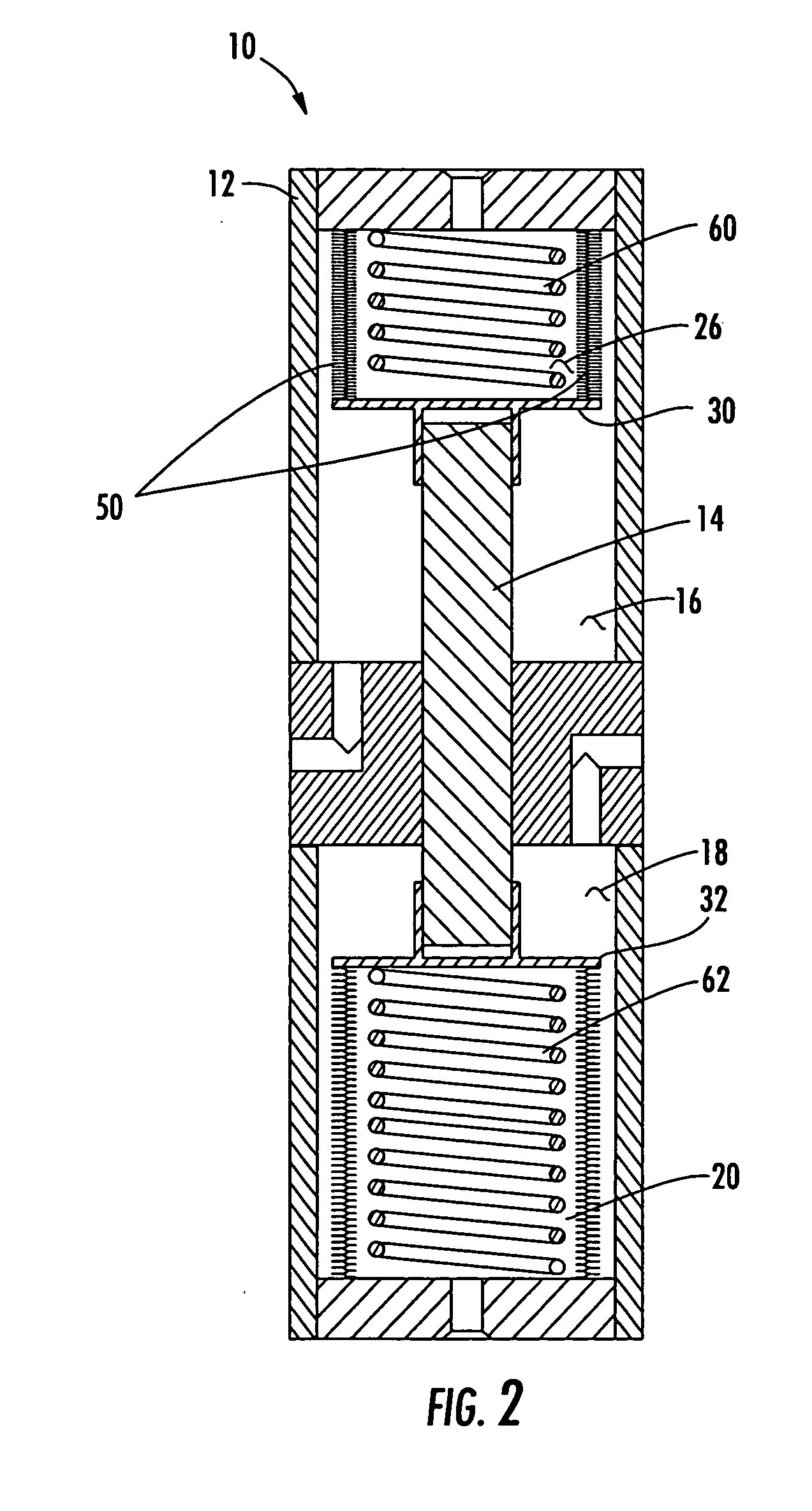
[0031] Hermetically sealed pressure balanced accumulator 10 in accordance with the present invention is shown schematically in FIG. 1. Housing 12 includes moveable divider mechanism 14 for separating housing 12 into at least accumulator chamber 16, balancing chamber 18, and balancing chamber 20. In hermetically sealed pressure balanced accumulator 10, hermetic sealing device 22 seals balancing chamber 18 from balancing chamber 20.

[0032] As discussed in the Background section above, in one example accumulator chamber 16 may be a hydraulic fluid chamber for storing hydraulic fluid. Typical...


PUM


Abstract

A hermetically sealed pressure-balanced accumulator includes a housing and a moveable divider mechanism for separating the housing into at least an accumulator chamber at a pre-selected accumulator pressure. A first balancing chamber is responsive to changes in ambient pressure for adjusting said pre-selected accumulator pressure with respect to ambient pressure. A second balancing chamber is responsive to the first balancing chamber, and the first and second balancing chambers maintain a predetermined pressure differential between the pre-selected accumulator pressure and ambient pressure. The hermetically sealed pressure-balanced accumulator further includes a hermetic sealing device for sealing the first balancing chamber from at least one of the accumulator chamber and the second balancing chamber.

Description

FIELD OF THE INVENTION [0001] This invention relates to an accumulator with improved sealing. BACKGROUND OF THE INVENTION [0002] Accumulators are devices that provide a reserve of hydraulic fluid under pressure and are used in conventional hydraulically driven systems where hydraulic fluid under pressure operates equipment or a device. Depending on the load of the device to be operated, a minimum pressure level is required for successful operation. The hydraulic fluid is pressurized by a pump that maintains the high pressure required. If the pump is not operating, accumulators can be used to provide a reserve source of pressurized hydraulic fluid to enable the operation of brakes, for example, on an aircraft when the engines are not operating. [0003] In addition, if the device is located a considerable distance from the pump, a significant pressure drop can occur in the hydraulic conduit or pipe which is conveying the fluid from the pump to operate the device. Therefore, the flow ma...

Claims


Application Information

Patent Timeline
Patent Type & Authority Applications(United States)
IPC IPC(8): F16L55/053
CPCF16L55/053
Inventor WHITE, ANDREW J.
Owner EATON CORP
Learn More