
Nail gun extension kit

a technology for nail guns and extension kits, which is applied in the field of extension kits, can solve the problems of not being able to provide a mechanism to compensate for different pitches in known extension designs, and a lot of physical strain on roofers, so as to achieve the effect of increasing control

Inactive Publication Date: 2005-07-21
GAZLAY JAMES M
View PDF13 Cites 6 Cited by
  • Summary
  • Abstract
  • Description
  • Claims
  • Application Information

AI Technical Summary

Benefits of technology

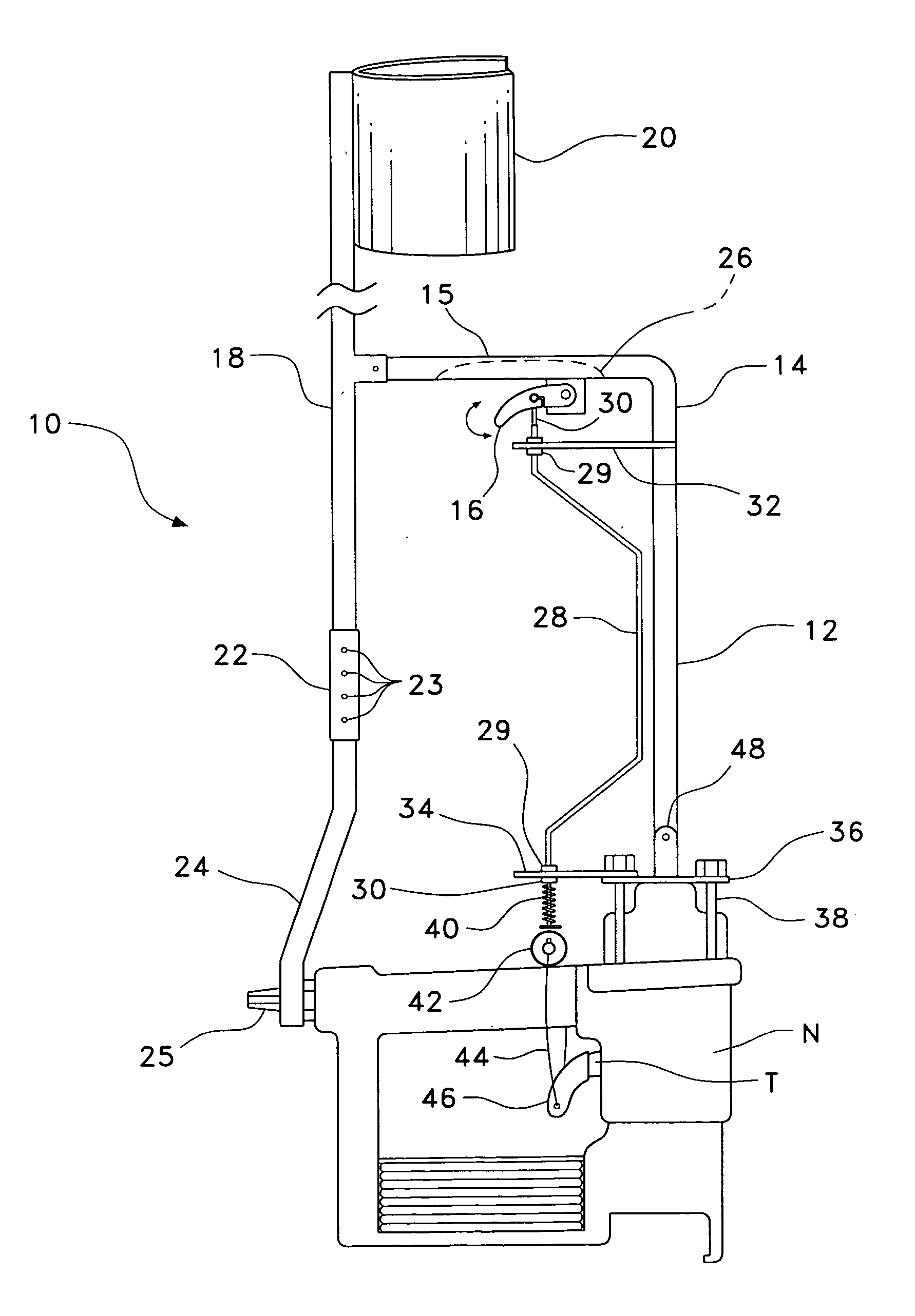
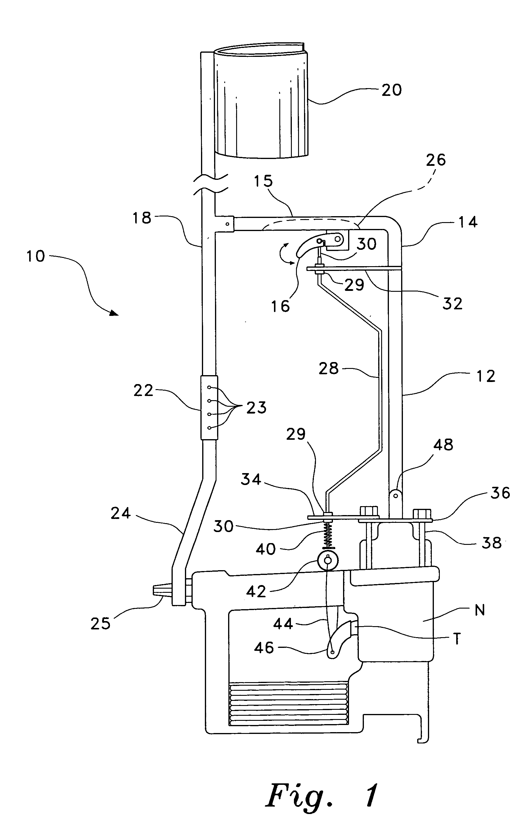
[0009] The nail gun extension kit is an extension tool designed specifically for pneumatic nail guns of the type used in roofing. A plate is set above the socket cap. Both the plate and socket cap are screwed in to the nail gun together. An L-shaped extension arm is pivotally mounted on the plate, allowing the user to adjust the angle of the nail gun relative to the handle for roofs of varying pitch. The top of the extension arm forms a handle, which houses a trigger. A forearm brace near the back of the handle and an adjustable back brace attaching the back of the handle to the back of the nail gun give the user increased control for use with one hand, as well as the ability to adjust the handle for the pitch of the roof. A Bowden cable runs from the handle trigger to a trigger sling secured on the nail gun trigger, allowing remote firing of the nail gun.
[0010] Hence, the nail gun extension kit of the present invention relieves back strain by permitting the user to operate a pneumatic nail gun while in the standing position. The nail gun extension kit further provides for adjustment to accommodate different roof pitch angles, thereby rendering the extension kit more useful to the roofer.

Problems solved by technology

However, in the process of shingling a roof, nailing a shingle is a step that must be repeated hundreds of times. Even doing something as easy as pulling a trigger can become physically taxing when it must be done on bended knees, combined with repeated crawling of minute distances to set the next set of shingles in place.
Roofers continue to suffer from back pain from bending over to nail roof shingles.
Known extension designs fail provide a mechanism to compensate for different pitches for ease of use on different pitched roofs.

Method used


Image

  • Nail gun extension kit
  • Nail gun extension kit
  • Nail gun extension kit

Examples


Embodiment Construction

[0025] The present invention is a nail gun extension kit, designated generally as 10 in the drawings. The nail gun extension kit 10 is specifically designed to attach to a roofing nail gun N, as shown completely attached and ready for use in FIG. 1. The length of the extension, the secure connection to the nail gun N, and additional forearm bracing provided by the invention 10 allow the user to easily control and fire the nail gun N from a standing position.

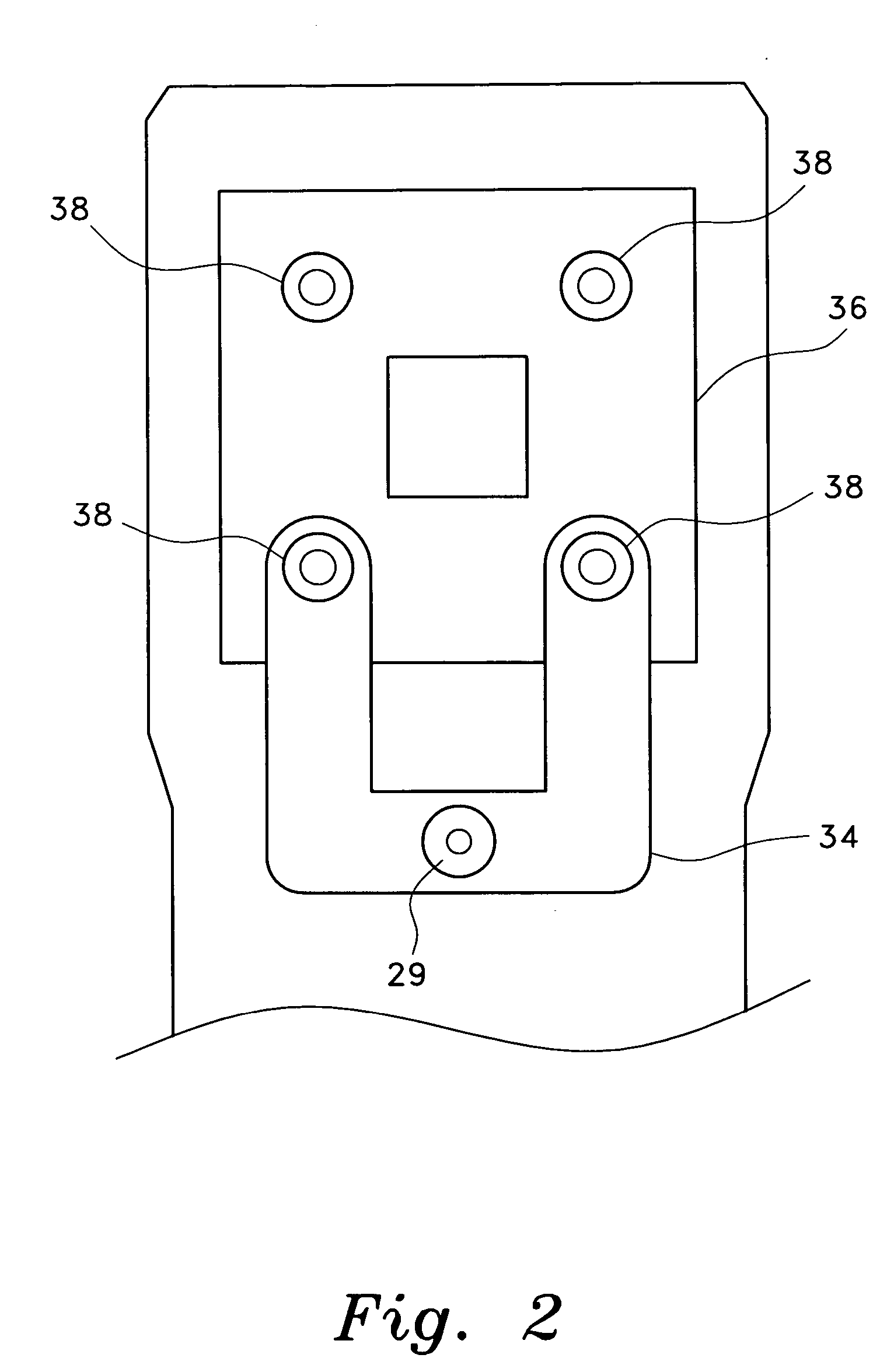
[0026] The conventional roofing nail gun has four screws securing a socket cap to the top of the nail gun. Referring first to FIG. 2, the nail gun extension kit 10 includes four shoulder screws 38 that are to be used to replace the original nail gun socket cap screws and secure the extension arm bracket plate 36 to the nail gun N. The extension arm bracket plate 36 has four holes, one in each corner, aligned with the standard configuration of the roofing nail gun socket cap screws. The shoulder screws 38 are long enough to pass ...


PUM


Abstract

The nail gun extension kit is an extension tool designed specifically for pneumatic nail guns used for roofing. A plate is set above the socket cap. Both the plate and socket cap are screwed in to the nail gun together. An L-shaped extension arm is pivotally mounted on the plate, allowing the user to adjust the angle of the nail gun relative to the handle for roofs of varying pitch. The top of the extension arm forms a handle, which houses a trigger. A vertical standard is attached to the handle and has a top end supporting a cuff that attached to the users arm, and a lower end attached to the rear end of the nail gun by an adjustable length link. A cable runs from the extension handle trigger to a trigger sling secured on the nail gun trigger, allowing remote firing of the nail gun.

Description

CROSS-REFERENCE TO RELATED APPLICATION [0001] This application claims the benefit of U.S. Provisional Patent Application Ser. No. 60 / 536,498, filed Jan. 15, 2004.BACKGROUND OF THE INVENTION [0002] 1. Field of the Invention [0003] The present invention relates to power tool extension sets, particularly to an extension kit for pneumatic nail guns of the type frequently used by roofers, so that the roofer can operate the nail gun while in a standing position. [0004] 2. Description of the Related Art [0005] The power nail gun, particularly the pneumatic nail gun, is an invaluable tool of the modern day roofer. In the pneumatic nail gun, the amount of effort required to nail a shingle down has been reduced from repeated strikes with a hammer to the simple pull of a trigger. However, in the process of shingling a roof, nailing a shingle is a step that must be repeated hundreds of times. Even doing something as easy as pulling a trigger can become physically taxing when it must be done on ...

Claims


Application Information

Patent Timeline
Patent Type & Authority Applications(United States)
IPC IPC(8): B25C1/04
CPCB25C1/04
Inventor GAZLAY, JAMES M.
Owner GAZLAY JAMES M
Learn More