Combination test method and test device

a test method and test device technology, applied in the direction of frequency to phase shift conversion, instruments, generating/distributing signals, etc., can solve the problems of difficult to evaluate the quality of data directly through serial data, high-cost jitter generating devices, and not providing a method for applying jitter to serial data that changes constantly, etc., to achieve accurate data reproduction and easy test

Inactive Publication Date: 2005-07-21
NEC ELECTRONICS CORP
View PDF7 Cites 37 Cited by
  • Summary
  • Abstract
  • Description
  • Claims
  • Application Information

AI Technical Summary

Benefits of technology

[0013] In the combination test method and test device according to the present invention, by applying jitter to a first clock signal having a lower frequency than a second clock signal having a second frequency, jitter is superimposed onto data of a second format output by a transmission device at a data rate corresponding to the second frequency. Conventionally, in order to apply jitter to data having a high data rate, it has been necessary to use a highly expensive jitter generating device that is compatible with a high-speed signal, but in the present invention, since the signal to which the jitter is applied is a first clock signal of low speed, then a highly expensive jitter generating device is not required. Therefore, it is possible to easily test whether or not a receiving device inputting data of a second format can accurately reproduce data of a first format.

Problems solved by technology

The serial data output by the serializer 210 is high-speed data at a data rate of several Gbps, and hence it is difficult to evaluate the quality of the data directly by means of the serial data.
However, in the loop-back test illustrated in FIG. 8, if jitter is to be applied directly to the serial data, similarly to Japanese Unexamined Patent Application Publication No. 2002-368827, then since the serial data is transferred at an extremely fast speed, a highly expensive jitter generating device will be required.
Moreover, the method disclosed in the Japanese Unexamined Patent Application Publication No. 10-224213 involves applying jitter to a periodic signal, and does not provide a method for applying jitter to serial data that changes constantly.
Therefore, a jitter generating device of this kind cannot be applied directly to a loop-back test.

Method used


Image

  • Combination test method and test device
  • Combination test method and test device
  • Combination test method and test device

Examples


Embodiment Construction

[0023] The invention will be now described herein with reference to illustrative embodiments. Those skilled in the art will recognize that many alternative embodiments can be accomplished using the teachings of the present invention and that the invention is not limited to the embodiments illustrated for explanatory purposed.

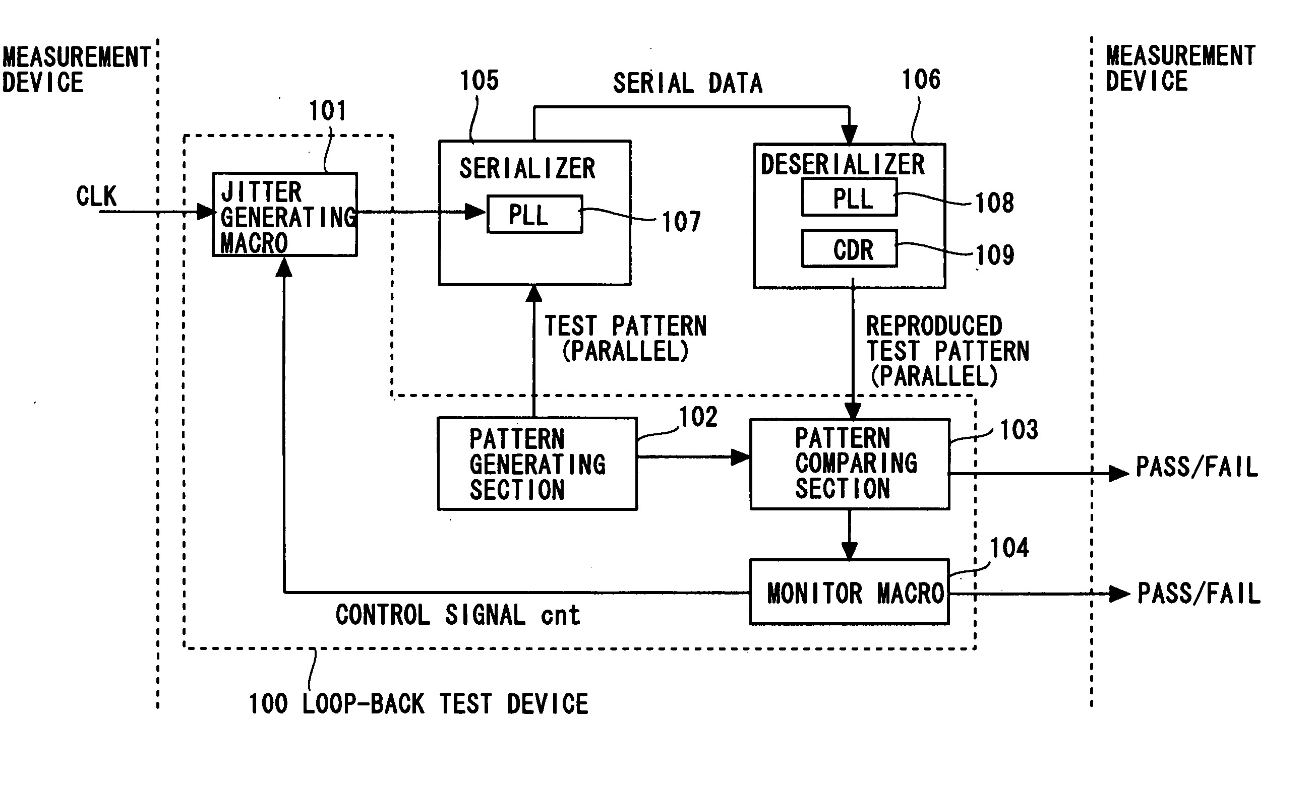
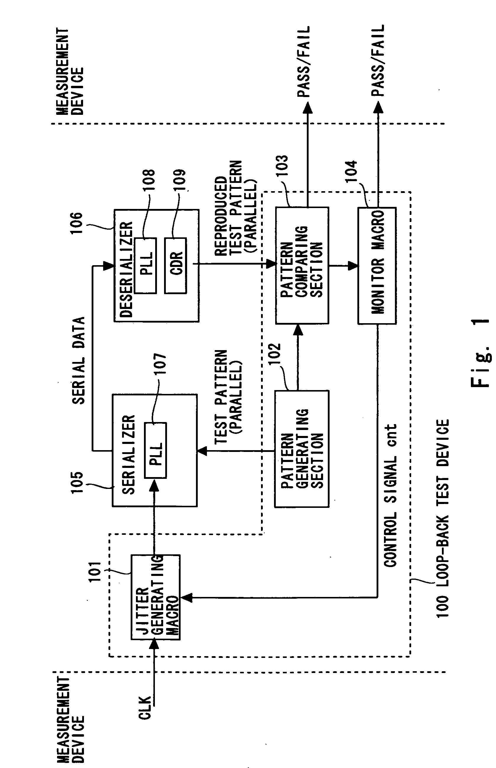
[0024]FIG. 1 shows a loop-back test device according to one embodiment of the present invention. This loop-back test device 100 comprises a jitter generating macro 101, a pattern generating section 102, a pattern comparing section 103, and a monitor macro 104. The loop-back test device 100 is incorporated into the same semiconductor device as that of a serializer 105 forming a transmission device and a deserializer 106 forming a receiving device. The loop-back test device 100 tests the functions of the serializer 105 and the deserializer 106 by means of a loop-back test which combines both the serializer 105 and the deserializer 106.

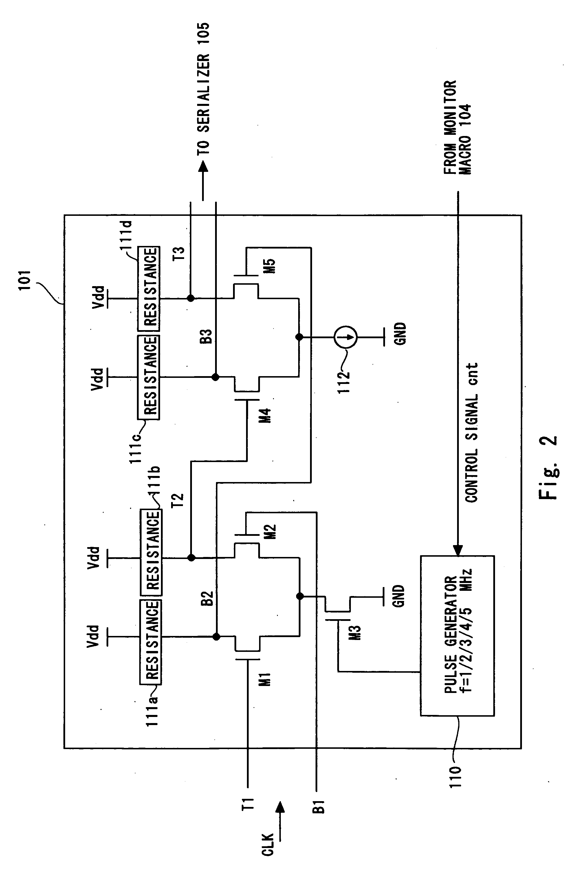
[0025] The pattern generati...


PUM


Abstract

In the combination test method according to the present invention, by applying jitter to a first clock signal having a lower frequency than a second clock signal having a second frequency, jitter is superimposed onto data of a second format output by a transmission device at a data rate corresponding to the second frequency. Conventionally, in order to apply jitter to data having a high data rate, it has been necessary to use a highly expensive jitter generating device that is compatible with a high-speed signal, but in the present invention, since the signal to which the jitter is applied is a first clock signal of low speed, then a highly expensive jitter generating device is not required. Therefore, it is possible to easily test whether or not a receiving device inputting data of a second format can accurately reproduce data of a first format.

Description

BACKGROUND OF THE INVENTION [0001] 1. Field of the Invention [0002] The present invention relates to a combination test method and test device, and more particularly, to a combination test method and test device in which a signal transmitted by a transmission device which converts data of a first format to data of a second format is input to a receiving device which reproduces data of the first format from data of the second format, and it is determined whether or not the signal transmitted by the transmission device matches the signal reproduced by the receiving device. [0003] 2. Description of Related Art [0004] In recent years, data transfer speeds in semiconductor devices have increased and data transfer at very high data rates of several Gbps (gigabits per second), for example, have been achieved. Generally, in the case of parallel transmission, it is difficult to adjust the skew between signals, and therefore the tendency is for serial transmission to be used for high-speed da...

Claims


Application Information

Patent Timeline
Patent Type & Authority Applications(United States)
IPC IPC(8): G01R23/12G01R31/3183G01R31/28G01R31/30G01R31/317G06F1/04
CPCG01R31/2882G01R31/31725G01R31/31709G01R31/3016
Inventor KANBAYASHI, TAKAMASA
Owner NEC ELECTRONICS CORP
Why Eureka
Try Eureka