Wallpaper printer with removable printhead

a technology of printhead and printhead, which is applied in the field of printers, can solve the problems of inconvenient cleaning and cleaning, and the size and content of inventory are hindering the sales of inventory, and achieve the effect of preventing contamination

Inactive Publication Date: 2005-07-21
SILVERBROOK RES PTY LTD
View PDF16 Cites 3 Cited by
  • Summary
  • Abstract
  • Description
  • Claims
  • Application Information

AI Technical Summary

Benefits of technology

[0135] Preferably the printer further comprises an air supply and a tube for bringing a supply of air to the printhead which supply prevents media from sticking to the printhead.
[0136] Preferably the pr

Problems solved by technology

Inventory based sales are hindered by

Method used


Image

  • Wallpaper printer with removable printhead
  • Wallpaper printer with removable printhead
  • Wallpaper printer with removable printhead

Examples


Embodiment Construction

1. Exterior Overview

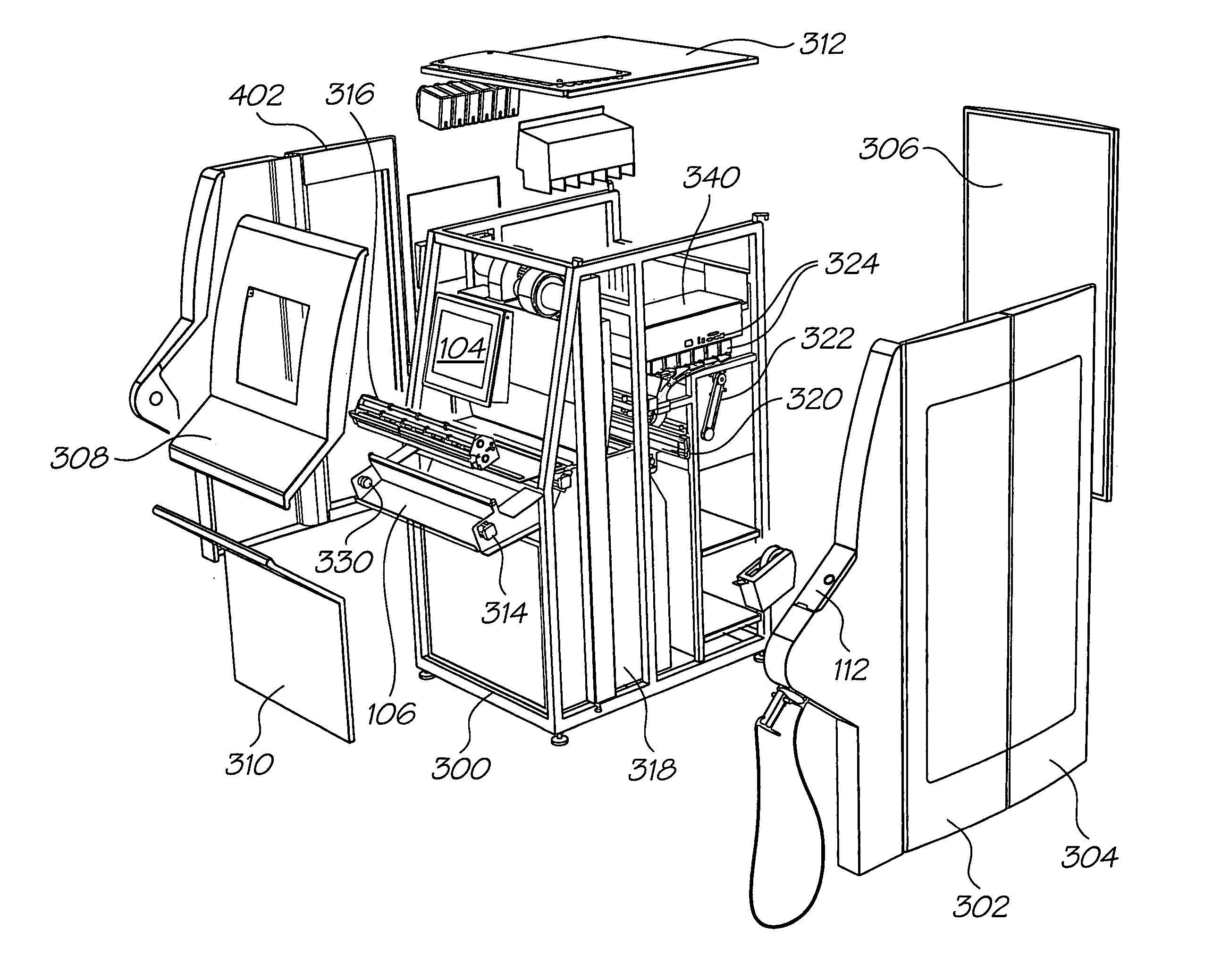
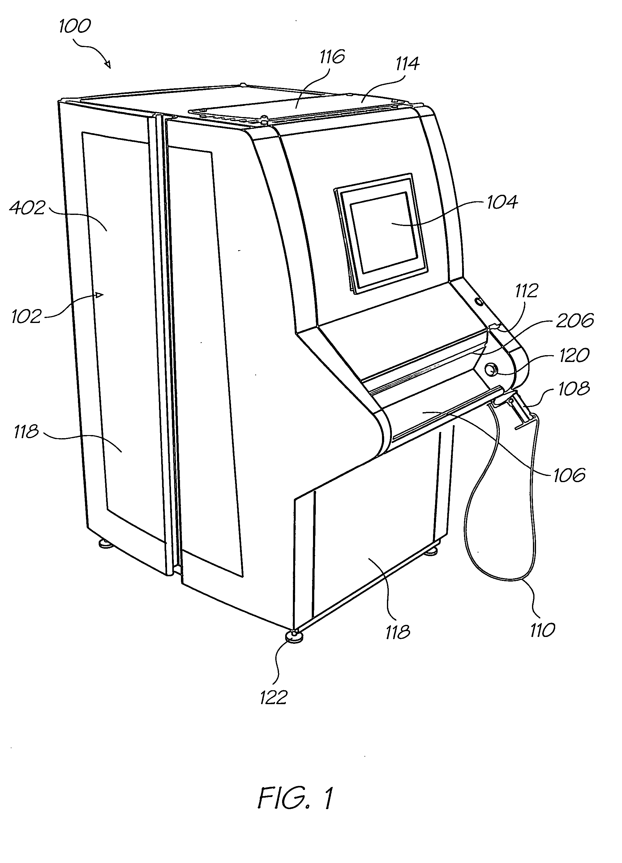
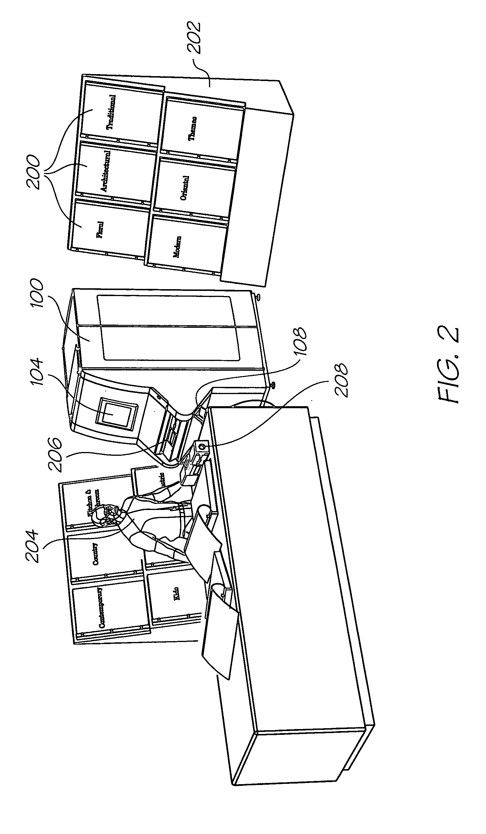
[0514] As shown in FIG. 1 a wallpaper printer 100 comprises a cabinet 102 with exterior features to facilitate the specification of, purchase of, and packaging of wallpaper which is selected and printed, on-demand, for example at a point of sale. The cabinet 102 includes a tilting touch screen interface 104 such as an LCD TFT screen which is positioned at a convenient height for a standing person. The cabinet also supports a pistol grip type barcode scanner 108 which serves as a data capture device and input. The scanner 108 is preferably attached to the cabinet 102 by a data cable or a tether 110, even if the scanner 108 operates over a wireless network.

[0515] The cabinet 102 includes a winding area, in this example taking the form of an exterior well 106 for receiving a container for printed wallpaper, as will be further explained. The well holds a specially configured container 208 (see FIGS. 4 and 5). The container holds a winding core onto which is wound ...


PUM


Abstract

A printer for producing rolls of wallpaper has a housing in which is located a media path which extends from a blank media intake to a wallpaper exit slot. A multi-color roll width printhead located in the housing and across the media path. The printhead is supplied by separate ink reservoirs and the reservoirs are connected to the printhead by an ink supply harness. A disconnect coupling is placed between the reservoirs and the printhead. Inputs to the printer include one or more input devices for capturing operator instructions. A processor accepts the operator inputs and configures the printer for producing a particular roll.

Description

FIELD OF THE INVENTION [0001] The invention pertains to printers and more particularly to a printer for wallpaper. The printer is particularly adapted to print long rolls of full color wallpaper and is well suited to serve as the basis of both retail and franchise operations which pertain to print-on-demand wallpaper. CO-PENDING APPLICATIONS [0002] Various methods, systems and apparatus relating to the present invention are disclosed in the following co-pending applications filed by the applicant or assignee of the present invention simultaneously with the present application: WAL01USWAL02USWAL03USWAL04USWAL05USWAL06USWAL07USWAL08USWAL09USWAL10USWAL11USWAL12USWAL13USWAL14USWAL15USWAL17USWAL18USWAL19USWAL20USMPA01USMPA02USMPA03USMPA04USMPA05USMPA06USMPA07USMPA08USMPA09USMPA10USMPA11USMPA12USMPA13USMPA14USMPA15USMPA16USMPA17USMPA18USMPA19USMPA20USMPA21USMPA22USMPA23USMPA24USMPA25USMPA26USMPA27USMPA28USMPA29USMPA30USMPA31USMPA32USMPA33USRRA01USRRA02USRRA03USRRA04USRRA05USRRA06USRRA07U...

Claims


Application Information

Patent Timeline
IPC IPC(8): B41J11/00B41J11/68B41J11/70B41J15/04
CPCB41J11/002B41J11/68B41J15/044B41J15/04B41J11/70B41J11/0022B41J11/0024B41J11/00244
Inventor SILVERBROOK, KIAKING, TOBIN ALLENLEE, JANETTE FAYE
Owner SILVERBROOK RES PTY LTD
Why Eureka
Try Eureka