
Mounting and supporting arrangement for printhead assembly

a technology for mounting and supporting arrangement, which is applied in the direction of inking apparatus, laminating printed circuit boards, coupling device connections, etc., can solve the problems of difficult manufacturing of such printheads, complicated assembly process, and inability to provide easy disassembly, so as to facilitate clamping

Active Publication Date: 2005-07-21
SILVERBROOK RES PTY LTD +1
View PDF0 Cites 20 Cited by
  • Summary
  • Abstract
  • Description
  • Claims
  • Application Information

AI Technical Summary

Benefits of technology

[0012] at least one mounting element held by the support frame, the at least one mounting element mounting the drive electronics and electrical conductors and incorporating a clamping arrangement for clamping the at least one printhead module to the support frame.
[0013] To facilitate the clamping, the support member includes longitudinally extending tabs on the two parallel sides thereof, with the support frame comprising a first side wall having a longitudinally extending recessed groove and a second side wall substantially parallel to the first side wall. Consequently, the longitudinally extending tab on one side of the support member is received in the longitudinally extending recessed groove of the support frame and the longitudinally extending tab on the other side of the support member is received on an upper surface of the second side wall of the support frame.

Problems solved by technology

In this regard, due to the large variation in the required dimensions of such printheads, it is difficult to manufacture such printheads in a manner which caters for this variability.
Such an arrangement complicates the assembly process and does not provide for easy disassembly should the need to replace components other than just the defective tiles be necessary.

Method used


Image

  • Mounting and supporting arrangement for printhead assembly
  • Mounting and supporting arrangement for printhead assembly
  • Mounting and supporting arrangement for printhead assembly

Examples


Embodiment Construction

[0087] The exemplary embodiments of the present invention are described as a printhead assembly and a printhead module that is incorporated in the printhead assembly.

General Overview

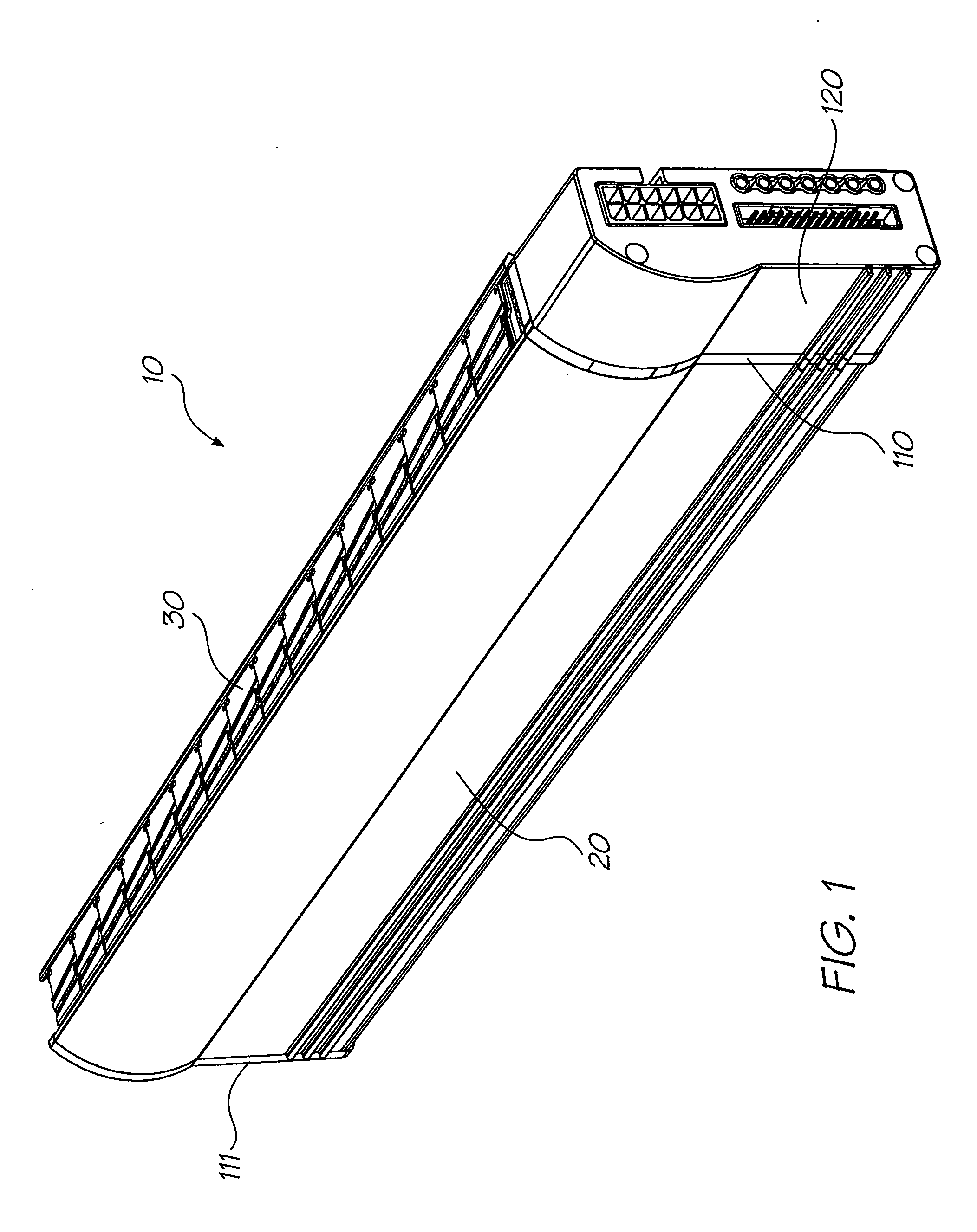
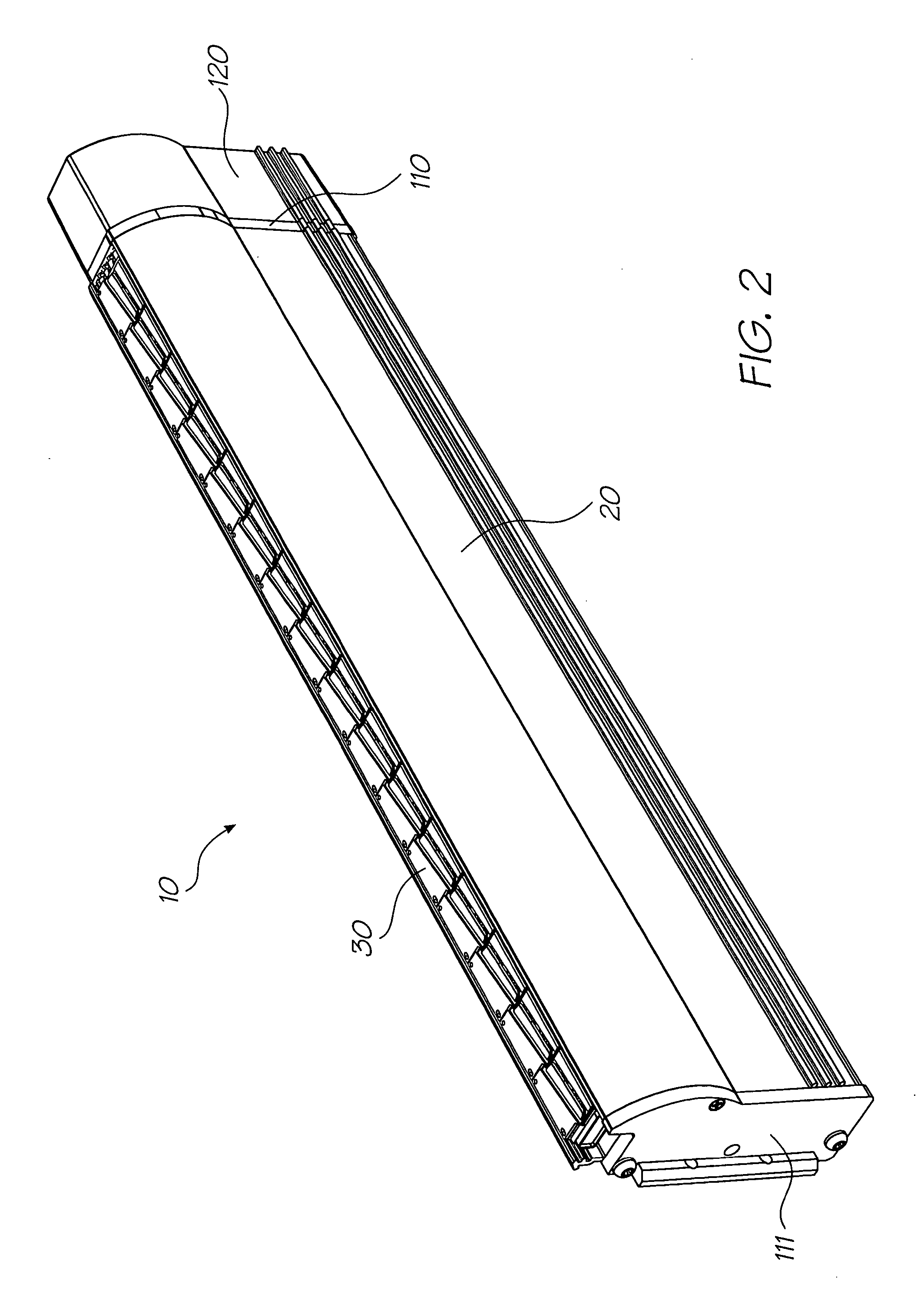
[0088] The printhead assembly 10 as shown in FIGS. 1 and 2 is intended for use as a pagewidth printhead in a printing system. That is, a printhead which extends across the width or along the length of a page of print media, e.g., paper, for printing. During printing, the printhead assembly ejects ink onto the print media as it progresses past, thereby forming printed information thereon, with the printhead assembly being maintained in a stationary position as the print media is progressed past. That is, the printhead assembly is not scanned across the page in the manner of a conventional printhead.

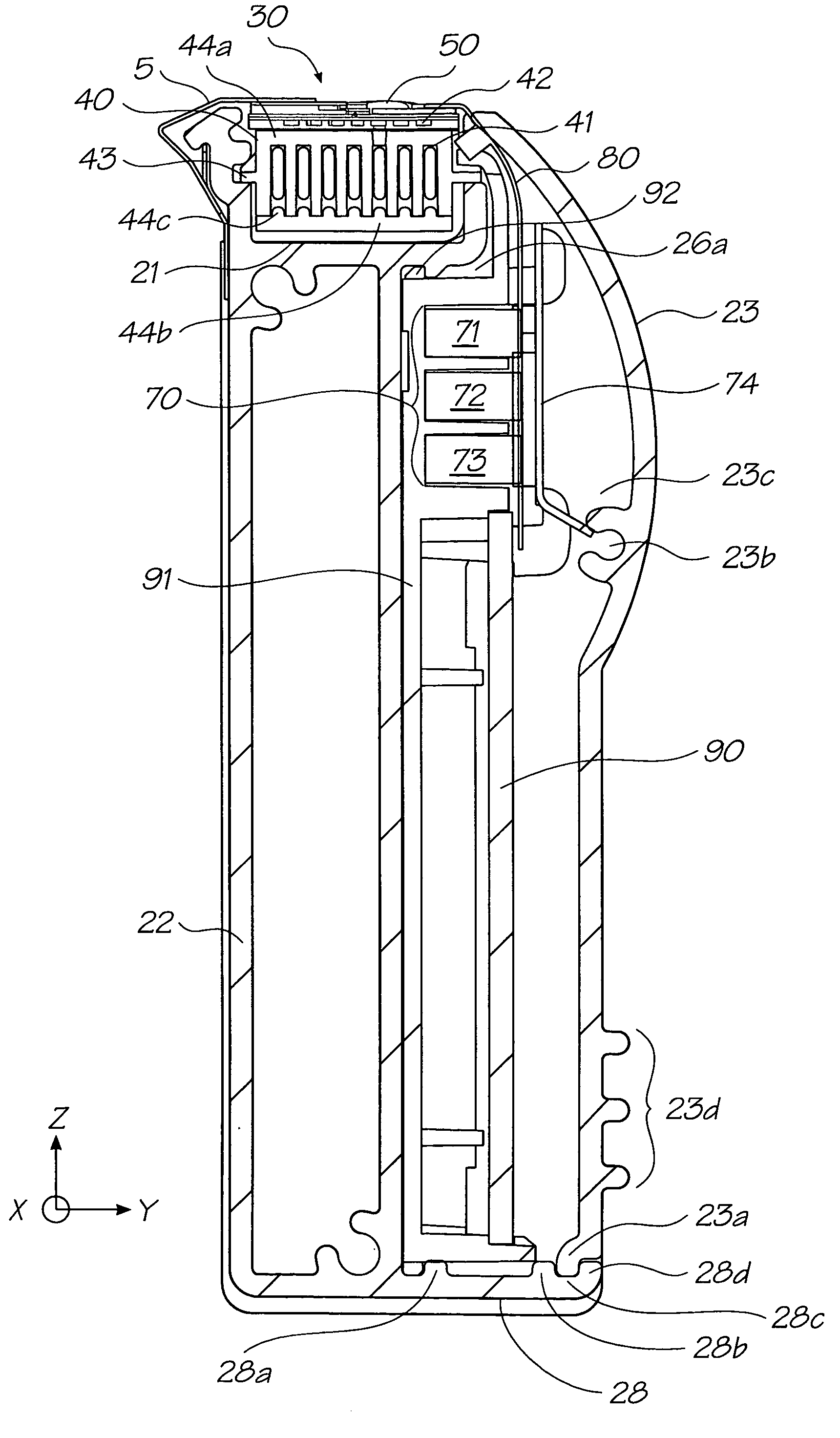
[0089] As can be seen from FIGS. 1 and 2, the printhead assembly 10 includes a casing 20 and a printhead module 30. The casing 20 houses the dedicated (or drive) electronics for the printhead assembly toget...


PUM


Abstract

A printhead assembly is provided comprising at least one printhead module comprising at least two printhead integrated circuits, each of which has nozzles formed therein for delivering printing fluid onto the surface of print media, a support member supporting the printhead integrated circuits and carrying the printing fluid, and an electrical connector for connecting electrical signals to the printhead integrated circuits. The assembly further comprises drive electronics arranged to control the printing operation of at least one printhead integrated circuit via the electrical connector, a plurality of longitudinally extending electrical conductors for providing power from a power supply to the drive electronics and the printhead integrated circuits, a casing comprising a support frame supporting the printhead module and at least one mounting element. The mounting element mounts the drive electronics and electrical conductors and incorporates a clamping arrangement for clamping the printhead module to the support frame.

Description

FIELD OF THE INVENTION [0001] The present invention relates to a printhead unit for use in a printing system. More particularly, the present invention relates to a printhead assembly which is mountable to and demountable from a printing unit. CROSS-REFERENCE TO CO-PENDING APPLICATIONS [0002] The following applications have been filed by the Applicant simultaneously with the present application: WAL01USWAL02USWAL03USWAL04USWAL05USWAL06USWAL07USWAL08USWAL09USWAL10USWAL11USWAL12USWAL13USWAL14USWAL15USWAL16USWAL17USWAL18USWAL19USWAL20USMPA01USMPA02USMPA03USMPA04USMPA05USMPA06USMPA07USMPA08USMPA09USMPA10USMPA11USMPA12USMPA13USMPA14USMPA15USMPA16USMPA17USMPA18USMPA19USMPA20USMPA21USMPA22USMPA23USMPA24USMPA25USMPA26USMPA27USMPA29USMPA30USMPA31USMPA32USMPA33USRRA01USRRA02USRRA03USRRA04USRRA05USRRA06USRRA07USRRA08USRRA09USRRA10USRRA11USRRA12USRRA13USRRA14USRRA15USRRA16USRRA17USRRA18USRRA19USRRA20USRRA21USRRA22USRRA23USRRA24USRRA25USRRA26USRRA27USRRA28USRRA29USRRA30USRRA31USRRA32USRRA33USSMA...

Claims


Application Information

Patent Timeline
Patent Type & Authority Applications(United States)
IPC IPC(8): B41J2/14B41J2/155
CPCB41J2/14427B41J2/155B41J2002/14435B41J2002/14491B41J2202/19B41J2202/20H01R12/721H01R13/6315H05K1/142H05K3/0058H05K2201/1028H05K2201/10424H01R12/79H01R13/2414
Inventor SILVERBROOK, KIABERRY, NORMAN MICHEALJACKSON, GARRY RAYMONDNAKAZAWA, AKIRA
Owner SILVERBROOK RES PTY LTD
Learn More