Image forming apparatus in which recording sheet having tab is used

a technology of image forming apparatus and recording sheet, which is applied in the direction of electrographic process apparatus, instruments, optics, etc., can solve the problems of skewed sheets, incomplete images that cannot be checked after, and sheets with tabs at the desired positions were not appropriately inserted, so as to improve usability for users, avoid formation, and improve usability

Inactive Publication Date: 2005-07-21
KONICA MINOLTA BUSINESS TECH INC
View PDF2 Cites 18 Cited by
  • Summary
  • Abstract
  • Description
  • Claims
  • Application Information

AI Technical Summary

Benefits of technology

[0143] 19. In the Structure (19), the position of the tab of the sheet fed by the feeding section is detected by the tab detecting section containing a plurality of detectors. This arrangement ensures reliable position detection and adequate control.
[0144] 20. In the Structure (20), an alarm section is provided to send an error alarm. When an image is formed on the tab, an alarm is issued from the alarm section to notify the state of error if the inputted information fails to agree with the result of detection. This arrangement improves the u

Problems solved by technology

Furthermore, the finished images could only be checked after the images were actually formed on the tabs.
In other words, when the order of the tabs was incorrectly arranged, sheets with tabs at the desired positions were not appropriately inserted.
Furthermore, due to different tab positions, lengths, and widths, if the tab was located at the leading edge of the sheet in the sheet conveyance direction in the prior art image forming apparatus, the sheet was skewed when the tab came in contact with the registration roller and others, and sheet control was difficult, with the result that images could be formed only at the rear end of the sheet in the sheet conveyance direction.
Therefore, it was not possible to form images on both sides o

Method used


Image

  • Image forming apparatus in which recording sheet having tab is used
  • Image forming apparatus in which recording sheet having tab is used
  • Image forming apparatus in which recording sheet having tab is used

Examples


first embodiment

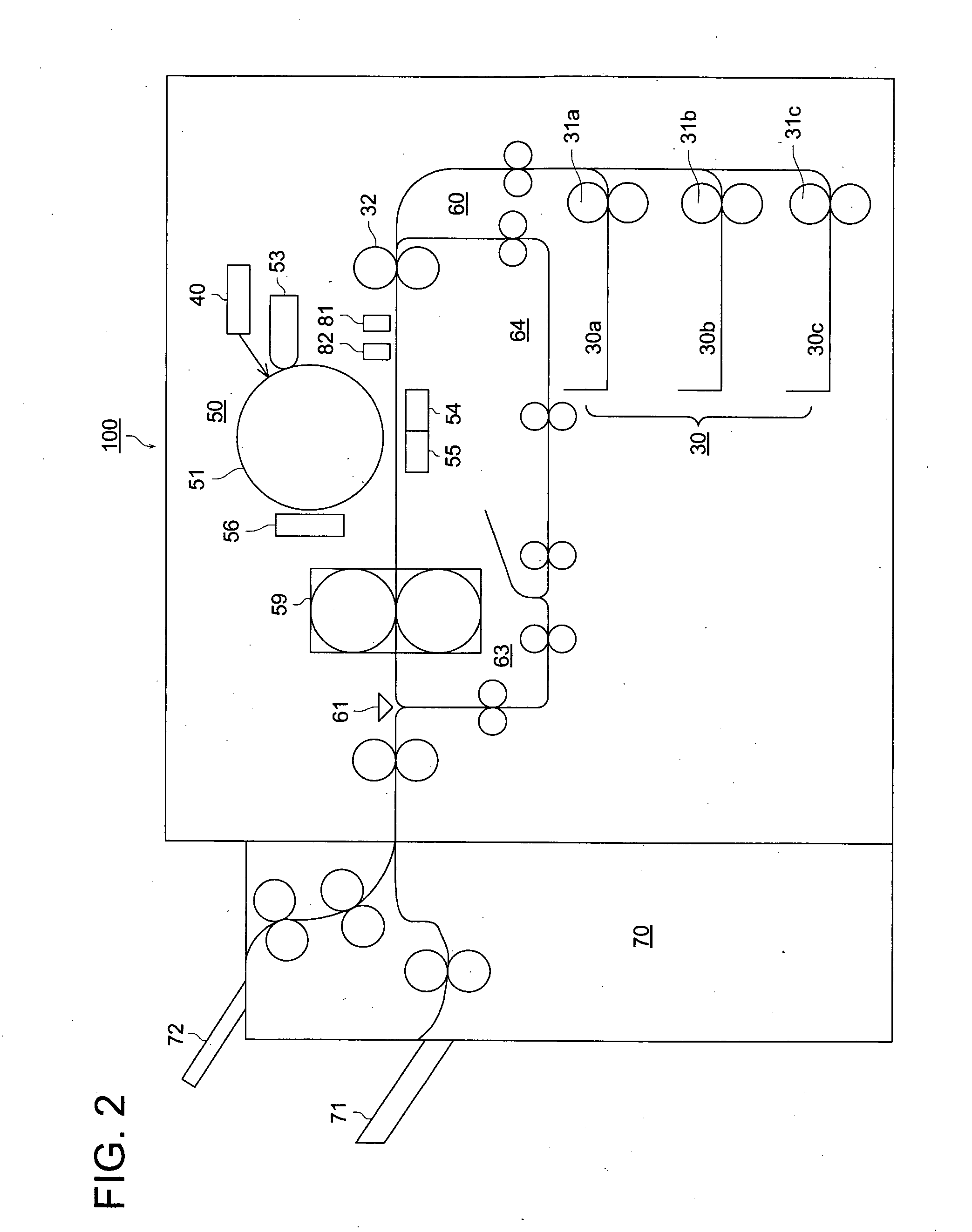
[0166] Referring to FIG. 2, a mechanical configuration within the overall configuration of an apparatus, to which an image forming device of the embodiment is applied, is described.

Mechanical Configuration and Overall Operation of the Image Forming Apparatus

[0167] First, a mechanical configuration of the image forming apparatus is described with reference to FIG. 2. Note that a copying machine that scans images from hard copies and conducts image formation is used as a specific example of the present embodiment. Further, here, an image forming apparatus is used for the specific example as a copying machine employing an electrophotographic method.

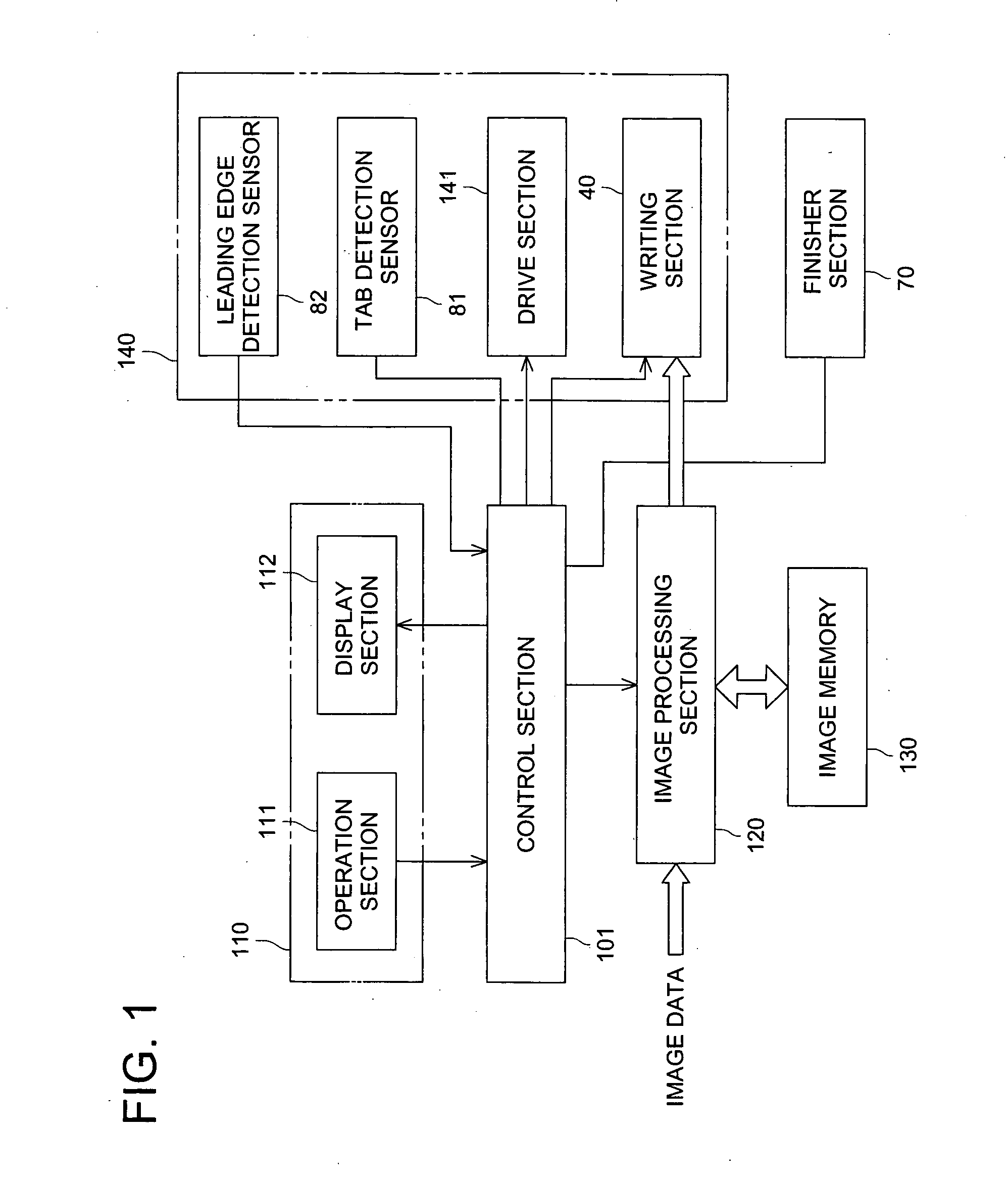
[0168] In FIG. 2, numeral 30 denotes a feeding section that feeds stacked sheets of paper, numeral 40 denotes a writing section that generates light beams for exposure in accordance with image data, numeral 50 denotes an image forming section that uses the electrostatic printing method to record image data onto recording medium p (genera...

second embodiment

[0273] FIGS. 8(a) to 8(d) are explanatory drawings that illustrate operations in the second embodiment of the present invention. Also, FIG. 9 is a flowchart illustrating operation in the second embodiment of the present invention, and the operations are basically the same as that of the flowchart in FIG. 3. The redundant explanations on the common items will be omitted, and only differences will be described.

[0274] Here, the control section 101 is able to detect based on the result of detection provided by the tab detection sensor 81 as shown in FIG. 8(b) that, as a result of tab positions and directions detection (S49), the sheet with a tab fed by the feeding section 30 is inclined as shown in FIG. 8(a).

[0275] Similarly, the control section 101 is able to detect based on the result of detection provided by the tab detection sensor 81 as shown in FIG. 8(d) that, as a result of tab positions and directions detection (S49 in FIG. 9), the sheet with a tab fed by the feeding section 3...


PUM


Abstract

An image forming apparatus includes: a feeding section for feeding sheets with tabs and sheets without tabs; a tab detecting section for detecting the end position, in the sheet conveyance direction, of tabs on the sheets fed by the feeding section; a conveying section for conveying sheets that are sequentially fed by the feeding section; and a control section for controlling the conveying section in such as way as to keep constant an interval between a trailing edge of a preceding sheet in the sheet conveyance direction and a leading edge of a succeeding sheet, based on the results of tab detection by the tab detecting section.

Description

BACKGROUND OF THE INVENTION [0001] The present invention relates to an image forming apparatus such as copying machines or printers, particularly to an image forming apparatus that is able to print on sheets with tabs. [0002] There have been cases where sheets with tabs were used with various types of image forming apparatus such as copying machines or printers. [0003]FIG. 15 is an explanatory drawing showing sheets with tabs. Seven sheets of paper are shown in this drawing, and the third sheet from the top (X in FIG. 15) and the fifth sheet from the top (Y in FIG. 15) are “sheets with tabs.”[0004] In FIG. 15, the portion x protruding from the third sheet from the top (X in FIG. 15) is the tab, and also, the portion y protruding from the fifth sheet from the top (Y in FIG. 15) is the tab. In FIG. 16, L stands for the tab length, and W stands for the tab width. Also in FIG. 15, although positions of the tabs x and y differ from each other in terms of the length-wise direction of the ...

Claims


Application Information

Patent Timeline
IPC IPC(8): G03G15/00
CPCG03G2215/00523G03G15/6594
Inventor KATO, KENJIWATANABE, HIROYUKI
Owner KONICA MINOLTA BUSINESS TECH INC
Why Eureka
Try Eureka