Method and system for header compression

a header and packet technology, applied in the field of packet-based communications, can solve the problems of protocol transmission errors, packet header overhead consumption, and limited options for compressing headers of protocol packets

Active Publication Date: 2005-07-21
III HLDG 3
View PDF23 Cites 123 Cited by
  • Summary
  • Abstract
  • Description
  • Claims
  • Application Information

AI Technical Summary

Benefits of technology

[0007] The present invention is directed to a method, system, and computer program product for the transmission of packets. The method, system, and computer program product establish with a receiving device a compression context for a plurality of packets. Each of these packets is associated with one or more reliable multicast protocols and includes a header having a plurality of header fields. Upon establishment of the compression context, a compressed packet is generated and transmitted to the receiving device. The compressed packet has a reduced number of bits in its header.

Problems solved by technology

In the case of Internet Protocol (IP) based communications, overhead associated with packet headers consumes a considerable amount of communications bandwidth.
However, the current options for compressing the headers of these protocol packets are limited.
In addition, this protocol has problems with transmission errors.
Another compression mechanism, known as DEFLATE also causes problems with transmission errors because it does not provide any support for error recovery.

Method used


Image

  • Method and system for header compression
  • Method and system for header compression
  • Method and system for header compression

Examples


Embodiment Construction

I. Operational Environment

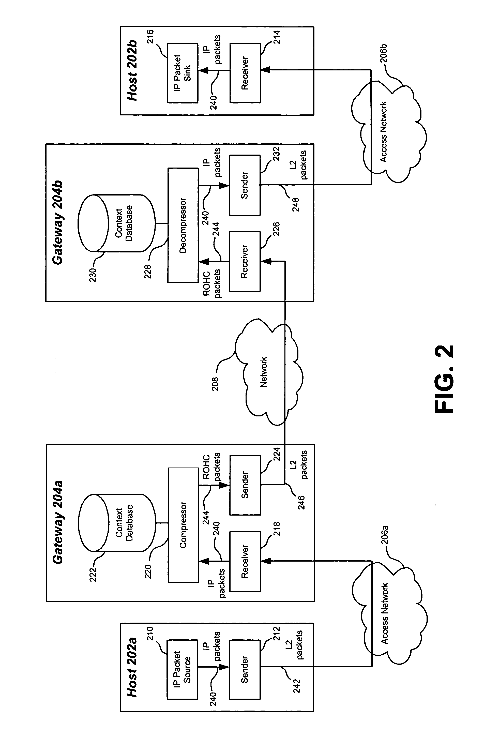
[0025] Before describing the invention in detail, it is helpful to describe environments in which the invention may be used. Accordingly, FIGS. 1 and 2 are block diagrams of operational environments where header compression techniques are employed to conserve communications bandwidth.

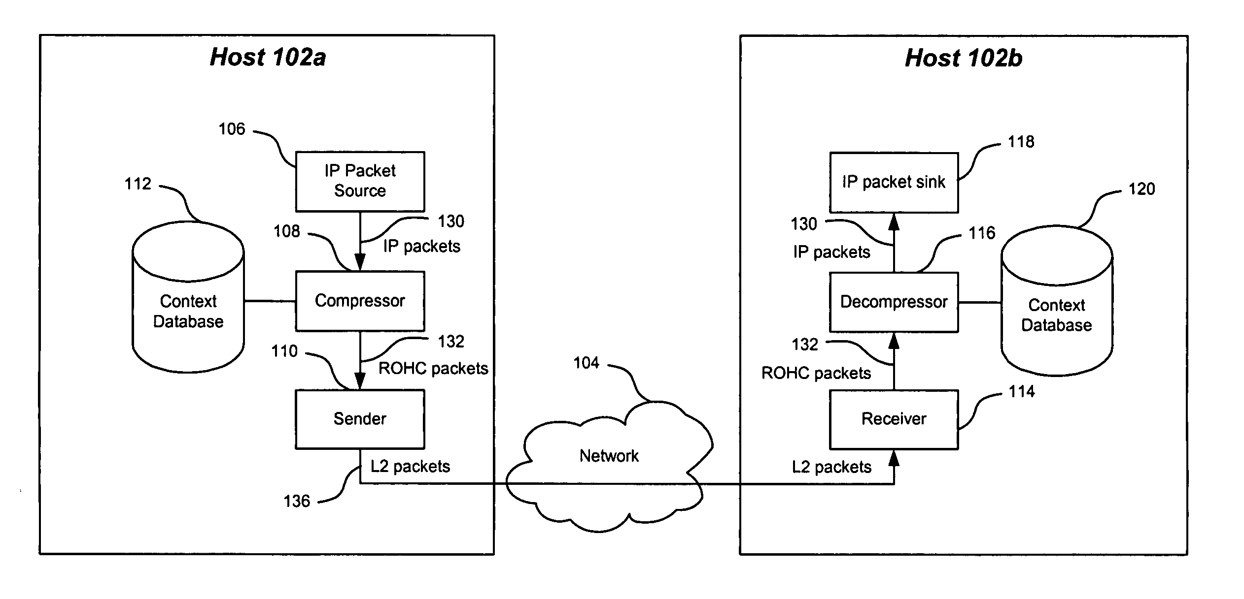
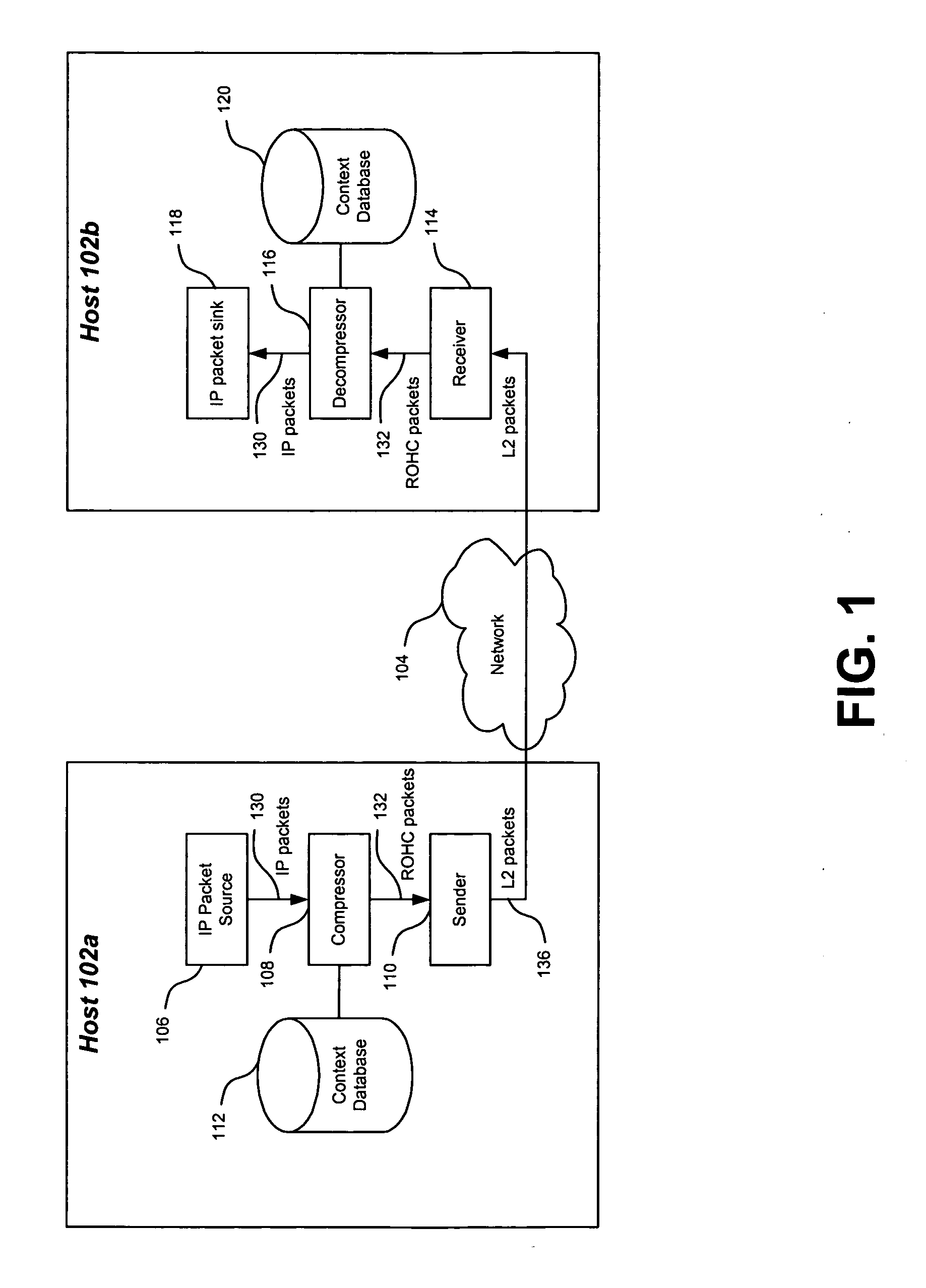
[0026]FIG. 1 shows an environment in which a first host 102a transmits packets across a packet-based network 104 to a second host 102b. To conserve the bandwidth of network 104, header compression is performed on these packets. This compression may be in accordance with various techniques, such as the ones described herein. Accordingly, host 102a compresses the protocol headers of one or more of the packets sent to host 102b. Upon receipt, host 102b decompresses these headers.

[0027]FIG. 1 shows that host 102a includes an Internet Protocol (IP) packet source 106, a compressor 108, a sender 110, and a compression context database 112. Host 102b includes a receiver 114, a decomp...


PUM


Abstract

A compression context for a plurality of packets is established with a receiving device. Each of these packets is associated with one or more reliable multicast protocols, such as the Layered Coding Transform (LCT) protocol, the Asynchronous Layered Coding (ALC) protocol, the FLUTE protocol, the MUPPET protocol, and the NACK-Oriented Reliable Multicast (NORM) protocol. Upon establishment of the compression context, a compressed packet is generated for one of the plurality of packets and transmitted to the receiving device. The compressed packet has a reduced number of bits in its header. Upon receipt, the receiving device decompresses the compressed packet based on the compression context.

Description

FIELD OF THE INVENTION [0001] The present invention relates to packet-based communications. More particularly, the present invention relates to techniques for compressing packets. BACKGROUND OF THE INVENTION [0002] In wireless communications systems, such as cellular networks, bandwidth is often a valuable resource that should be conserved. Thus, there is a need for compression techniques. Currently, there are known compression techniques that are suitable for the compression of arbitrary data units, such as protocol packet payloads. These techniques involve compression algorithms, which vary from being mathematical (e.g., gzip) to grammatical (e.g., SDP dictionaries translating text fields to a bit encoded format). [0003] In the case of Internet Protocol (IP) based communications, overhead associated with packet headers consumes a considerable amount of communications bandwidth. For instance, an Internet Protocol, version 4 (IPv4) packet header requires 20 bytes, while an Internet ...

Claims


Application Information

Patent Timeline
Patent Type & Authority Applications(United States)
IPC IPC(8): G06F15/16H04L12/18
CPCH04L12/1868H04L12/1877H04L69/22H04L69/04H04L12/189
Inventor WALSH, RODLUOMA, JUHA-PEKKASAARANEN, ANNE
Owner III HLDG 3
Why Eureka
Try Eureka