Base frame for fixture

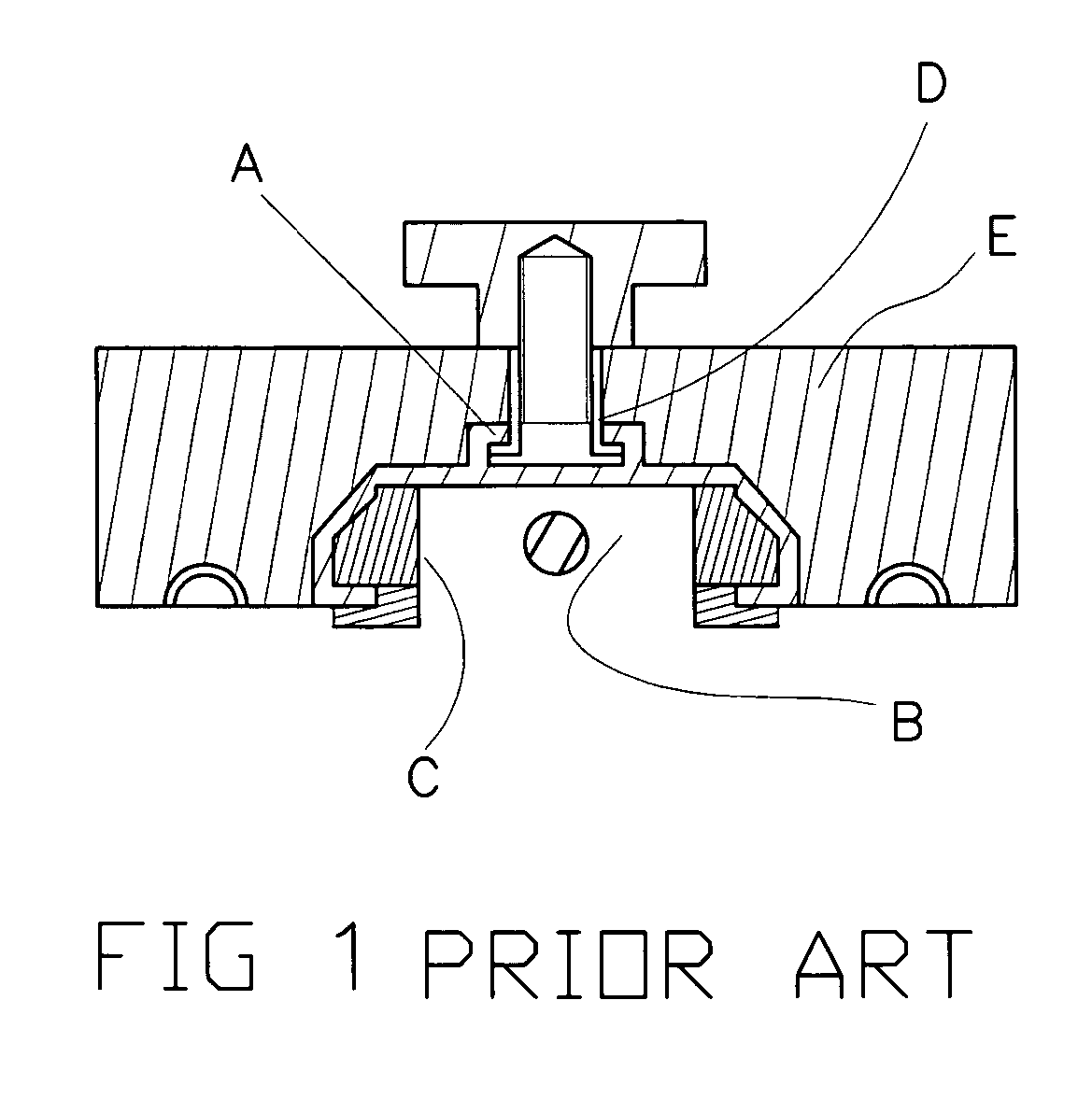
a fixture and base frame technology, applied in the field of fixture base frames, can solve the problems of unsatisfactory woodwork for the fixture base frame shown in fig. 1

Inactive Publication Date: 2005-07-28
CHIU MING HSIANG +1
View PDF6 Cites 11 Cited by
  • Summary
  • Abstract
  • Description
  • Claims
  • Application Information

AI Technical Summary

Benefits of technology

[0003] A primary object of the present invention is to provide an improved base frame for fixture. The base frame includes an extruded body having an integrally formed lower channel, to which different fixtures may be connecte...

Problems solved by technology

The conventional base frame for fixture shown...

Method used


Image

  • Base frame for fixture
  • Base frame for fixture
  • Base frame for fixture

Examples


Embodiment Construction

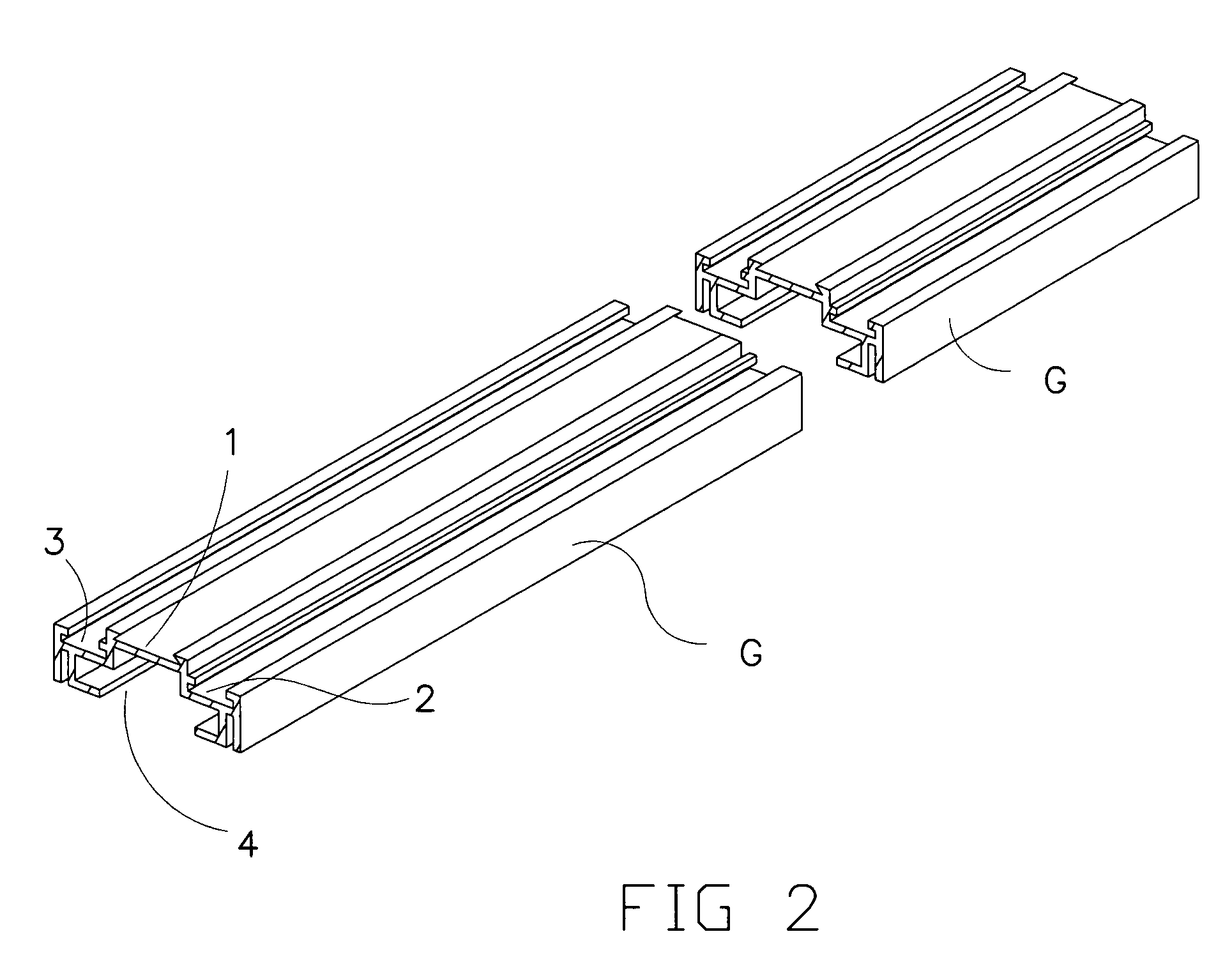
[0021] Please refer to FIG. 2. A base frame for fixture G according to the present invention is an extruded body having a raised top central portion and a lowered wing portion at each lateral side of the raised top central portion. The top central portion of the base frame G is an open-topped upper channel 1 in the form of a dovetail groove having a predetermined depth. The two lowered lateral wing portions are formed into two symmetrically identical open-topped side channels 2, 3. And, a large-size open-bottomed lower channel 4 is formed below the upper channel 1 and the two side channels 2, 3.

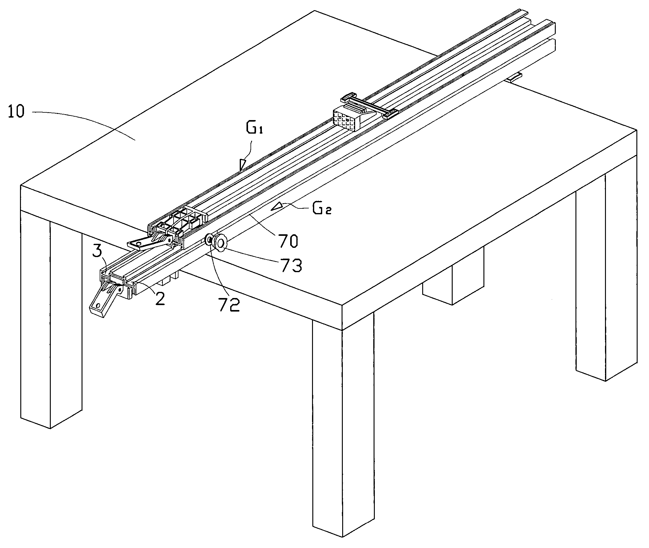
[0022] Please refer to FIG. 5. Two base frames G1, G2 may be symmetrically superposed with two upper channels 1 facing toward each other, so that the open-topped side channels 2, 3 at the same side of the superposed base frames G1, G2 together define an open-sided channel 7 between them.

[0023] Please now refer to FIGS. 3, 4, and 7. Two base frames G1, G2 of FIG. 2 may be perpendicularly con...


PUM

PropertyMeasurementUnit
Angleaaaaaaaaaa
Heightaaaaaaaaaa
Configurationaaaaaaaaaa

Abstract

A base frame for holding fixtures used in woodwork includes an extruded body having a raised top central portion formed into a dovetailed open-topped upper channel, two lowered wing portions located at each lateral side of the upper channel and formed into two symmetrically identical open-topped side channels with a height difference between the tops of the upper and the side channels, and a big-size open-bottomed lower channel formed below said upper channel and said two side channels. With the height difference between the upper and the side channels, two base frames may be perpendicularly connected to each other in the same plane using a U-shaped connecting bracket flush with the top of the upper channel, or superposed with the upper channels facing toward each other by locking inserting blocks in each open-sided channel formed between two side channels at the same side of the two superposed base frames.

Description

FIELD OF THE INVENTION [0001] The present invention relates to a base frame for holding fixtures used in woodwork. The base frame includes an extruded body having a raised top central portion formed into a dovetailed open-topped upper channel, two lowered wing portions located at each lateral side of the upper channel and formed into two symmetrically identical open-topped side channels with a height difference existed between the tops of the upper and the side channels, and a big-size open-bottomed lower channel formed below said upper channel and said two side channels. With the height difference between the upper and the side channels, two base frames may be perpendicularly connected to each other in the same plane using a U-shaped connecting bracket flush with the top of the upper channel, or superposed with the upper channels facing toward each other by locking inserting blocks in each open-sided channel formed between two side channels at the same side of the two superposed ba...

Claims


Application Information

Patent Timeline
IPC IPC(8): B25B1/08B25B1/24B25H1/00
CPCB25B1/08B25B1/2484Y10T409/306384Y10S269/901B25H1/0078
Inventor CHIU, MING-HSIANGLIU, HSU HSIU-KWEI
Owner CHIU MING HSIANG
Why Eureka
Try Eureka