Liquid crystal display device

a display device and liquid crystal technology, applied in the field of liquid crystal display devices, can solve the problems of reducing the width limit of the frame formed by injection molding resin in view of moldability and reliability, and the demand for narrow edge area on the lateral sides of the image display area is quite sever

Active Publication Date: 2014-09-11
JAPAN DISPLAY INC
View PDF12 Cites 44 Cited by
  • Summary
  • Abstract
  • Description
  • Claims
  • Application Information

AI Technical Summary

Benefits of technology

[0007]An advantage of some aspects of the invention is to provide a liquid cryst

Problems solved by technology

In particular, the demand for the narrow edge area on the lateral sides of an image display area is quite severe.
However, the frame form

Method used


Image

  • Liquid crystal display device
  • Liquid crystal display device
  • Liquid crystal display device

Examples


Embodiment Construction

[0026]Hereinafter, embodiments of the invention will be described with reference to the accompanying drawings.

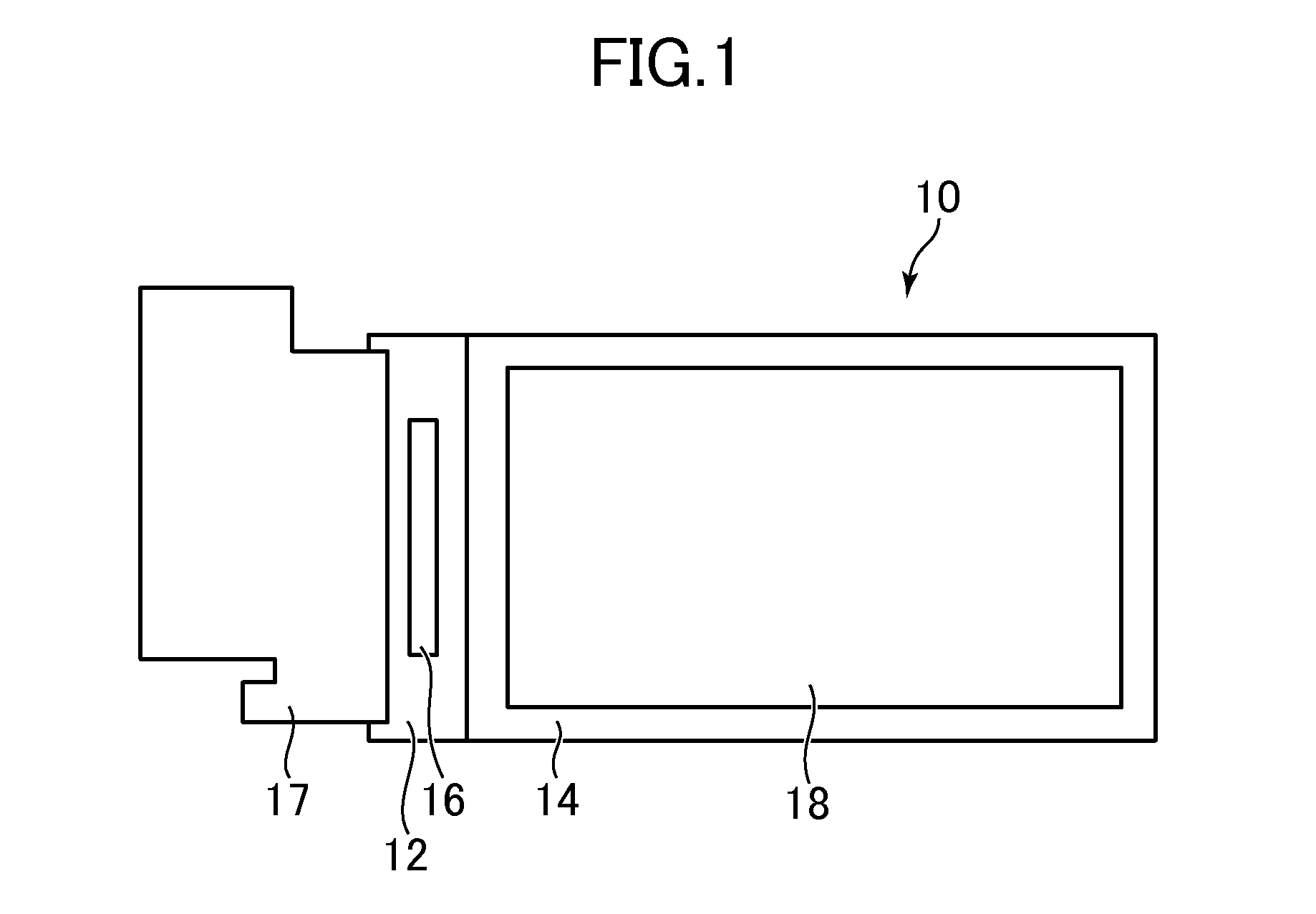
[0027]FIG. 1 is a plan view illustrating a liquid crystal display device according to an embodiment of the invention. The liquid crystal display device includes a liquid crystal display panel 10. The liquid crystal display panel 10 includes a pair of substrates 12 and 14 (either of which is a glass substrate, for example). A liquid crystal (not shown) is interposed between the substrates 12 and 14. One substrate 12 is a thin film transistor (TFT) substrate (or array substrate) that is provided with TFTs, pixel electrodes, wirings and the like, which are not shown, and the other substrate 14 is a color filter substrate.

[0028]The substrate 12 of the liquid crystal display panel 10 includes a protruding portion that protrudes from the substrate 14. An integrated circuit chip 16 in which a driver circuit for driving the liquid crystal is built is mounted on the liquid crystal di...


PUM


Abstract

A liquid crystal display device includes: a light guide plate that includes upper, lower and side surfaces; a light emitting element disposed to face an edge surface that is a part of the side surfaces; a reflection sheet that is bent to face the lower surface of the light guide plate and parts of the side surfaces thereof except for the edge surface; and an adhesive material disposed on the reflection sheet in a planar shape of dots or stripes and attaches the reflection sheet to the light guide plate. The lower surface of the light guide plate includes concaves and convexes formed to cause light that advances in the light guide plate to be reflected inside and to advance toward the upper surface. The thickness of the adhesive material is smaller than a maximum value of a height difference of the concaves and convexes.

Description

CROSS-REFERENCE TO RELATED APPLICATION[0001]The present application claims priority from Japanese application JP2013-42644 filed on Mar. 5, 2013, the content of which is hereby incorporated by reference into this application.BACKGROUND OF THE INVENTION[0002]1. Field of the Invention[0003]The present invention relates to a liquid crystal display device.[0004]2. Description of the Related Art[0005]A backlight of a liquid crystal display device includes a light guide plate that converts a point light source to a surface light source, in which a light emitting element is disposed to face an edge surface of the light guide plate (see JP 2010-62016 A). Light emitted from the light emitting element that is the point light source is incident onto the edge surface of the light guide plate, and is emitted by reflection to a liquid crystal display panel from a front surface of the light guide plate. The light emitting element and the light guide plate are accommodated in a frame. The frame is ...

Claims


Application Information

Patent Timeline
IPC IPC(8): F21V8/00
CPCG02B6/0001G02B6/0055G02B6/0038
Inventor SHIBATA, MICHIHIDE
Owner JAPAN DISPLAY INC
Why Eureka
Try Eureka